Do you have a question about the Deif PPU and is the answer not in the manual?
Defines the target audience for the manual.
Explains how the document is organized for clarity.
Clarifies special terms and symbols used throughout the manual.
Outlines DEIF's responsibilities and warranty conditions.
Precautions for handling components to prevent ESD damage.
Highlights risks of working with live electrical equipment.
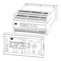
Provides a visual layout of terminal slots and ports on the unit.
Details I/O connections for DG units equipped with a PMS processor.
Details I/O connections for DG units not equipped with a PMS processor.
Describes I/O connections for shaft generators operating at a fixed frequency.
Details I/O connections for bus tie breakers connecting DG and SG.
Provides instructions for installing the Additional Operator Panel (AOP-2).
Explains how to configure the CAN ID for the AOP-2 unit.
Details the process for changing the CAN ID of the main display unit.
Illustrates the wiring diagram for 3-phase AC power connections.
Shows wiring for internal CANbus communication between units.
Details wiring specific to the Modbus RTU communication option.
Describes wiring procedures using 3-wire shielded cables.
Wiring diagrams and recommendations for load sharing communication.
Wiring for speed control using standard mechanical governors.
Wiring for Automatic Voltage Regulator (AVR) control using relay outputs.
Wiring configuration for electronic speed governors.
Wiring for AVR control using analogue outputs, requiring Option D.
General wiring information for binary inputs.
Wiring for binary inputs that include wire break supervision.
Wiring details for analogue signal inputs.
Wiring for optocoupler outputs used with external counters.
Comprehensive technical data including accuracy, operating conditions, and ratings.
Provides the physical dimensions of the PPM unit.
Specifies the required dimensions for panel mounting cutouts.
| Brand | Deif |
|---|---|
| Model | PPU |
| Category | Portable Generator |
| Language | English |