PPM Installation Instructions
DEIF A/S Page 47 of 69
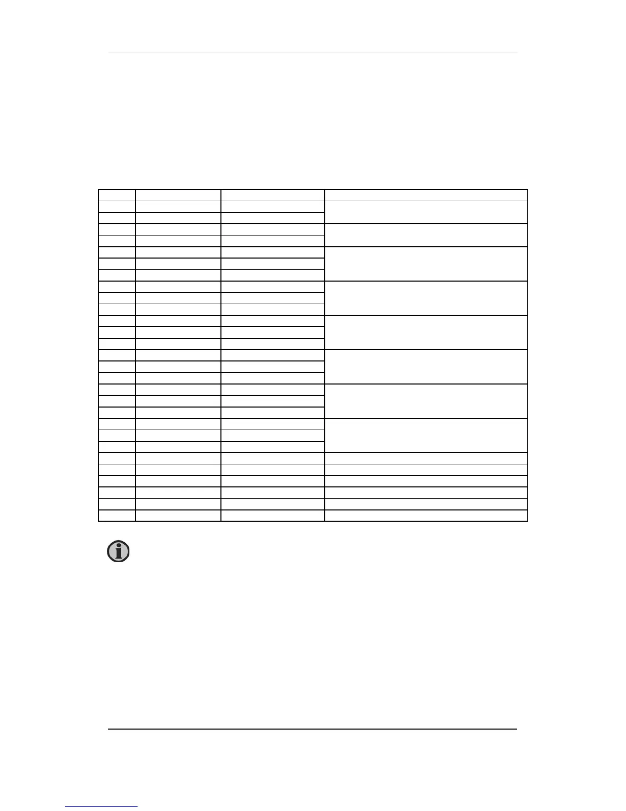
Terminal strip description
Slot #1, power supply and binary I/O
For the relay outputs the following terms will be used:
NO means Normally Open
NC means Normally Closed
Com. means common terminal for the relay in question
Term. Function Technical data Description
1 +12/24V DC 12/24V DC -25/+30% Power supply
2 0V DC
3 NC Status relay Normally closed relay, processor/power supply
status supervision
4 Com. 24 V/1A
5 NO Relay 1 Configurable. User-programmable
6 Com. 250V AC/8A
7 NC
8 NO Relay 2 Configurable. User-programmable
9 Com. 250V AC/8A
10 NC
11 NO Relay 3 PMS alarm
12 Com. 250V AC/8A
13 NC
14 NO Relay 4 CB OFF
Open breaker (deload)/trip
15 Com. 250V AC/8A
16 NC
17 NO Relay 5 CB ON
Close breaker (synchronising)
18 Com. 250V AC/8A
19 NC
20 Open collector 1 Transistor out Relay 26, configurable
Relay 27, configurable
Common terminal for terminals 20 and 21
21 Open collector 2 Transistor out
22 Com. Common
23 Binary input Optocoupler Configurable. User-programmable
24 Binary input Optocoupler Configurable. User-programmable
25 Binary input Optocoupler Configurable. User-programmable
26 Binary input Optocoupler Configurable. User-programmable
27 Binary input Optocoupler PMS control
28 Com. Common Common for terminals 23-27
The power supply must be protected with a 1A fuse.