PPM Installation Instructions
DEIF A/S Page 8 of 69
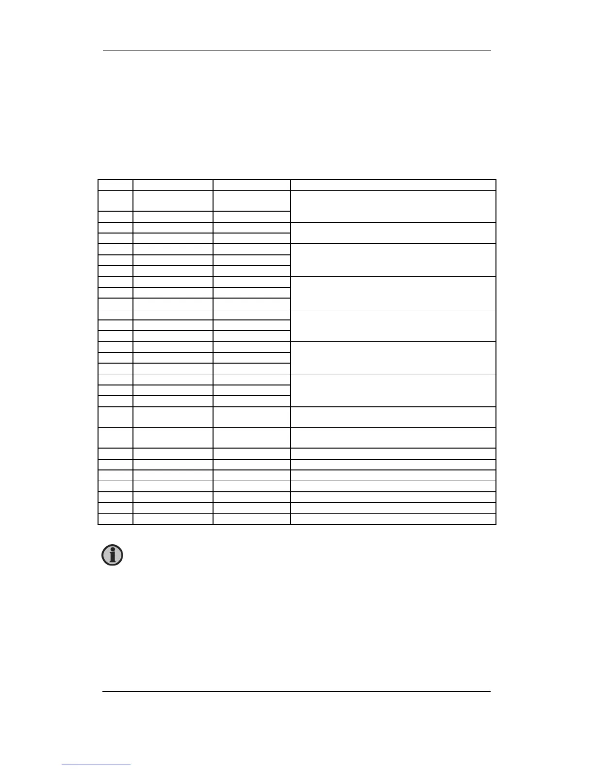
Terminal strip description
Slot #1, power supply and binary I/O
For the relay outputs the following terms will be used:
NO means Normally Open
NC means Normally Closed
Com. means common terminal for the relay in question
Term. Function Technical data Description
1 +12/24V DC 12/24V DC
-25/+30%
Power supply
2 0V DC
3 NC Status relay Normally closed relay, processor/power supply status
supervision
4 Com. 24 V/1A
5 NO Relay 1 Configurable/Trip NEL 1
6 Com. 250V AC/8A
7 NC
8 NO Relay 2 Configurable/Trip NEL 2
9 Com. 250V AC/8A
10 NC
11 NO Relay 3 PMS alarm
12 Com. 250V AC/8A
13 NC
14 NO Relay 4 CB OFF
Open breaker (deload)/trip
15 Com. 250V AC/8A
16 NC
17 NO Relay 5 CB ON
Close breaker (synchronising)
18 Com. 250V AC/8A
19 NC
20 Open collector 1 Transistor out configurable as standard relay output (relay number
26)
21 Open collector 2 Transistor out configurable as standard relay output (relay number
27)
22 Com. Common Common terminal for terminals 20 and 21
23 Binary input Optocoupler Configurable/Secured mode ON
24 Binary input Optocoupler Configurable/Secured mode OFF
25 Binary input Optocoupler Shore connection breaker position OFF
26 Binary input Optocoupler Forced switchboard control
27 Binary input Optocoupler PMS control
28 Com. Common Common for terminals 23-27
The power supply must be protected with a 1A fuse.