No unauthorized copying allowed
Format Number Issue
Note Redrawn
Redrawn
Date
Date
Date
Description
Description
Note
DrawnMeasures in mm,unless
otherwise specified
Scale
Luchthavenweg 42, 5657 EB
Eindhoven, the NETHERLANDS
A3
Page 1 /1
02-02-2007
24V
0V
POWER
0V
24V
HNF
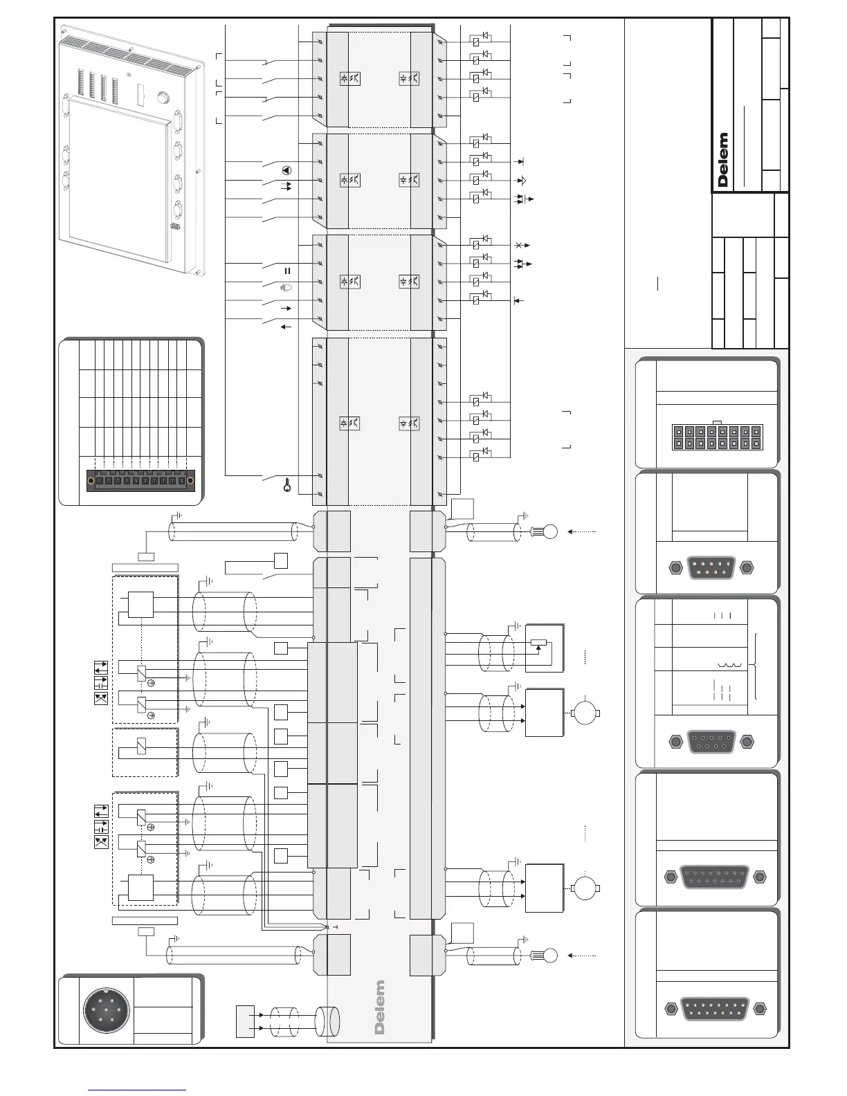
Example connections:
Note 1 : Leave unconnected pins open.
Note 2 : 24V relais supply must be separated from 24V supply
ANALOG A
0V
I/O
24V
I/O
0V
I/O
24V
I/O
See drawing 8061-901
for mounting dimensions
Delem 1128-00N
ANALOG A
15 POLE MALE
1
OUTAN1 -10V...+10V
IN1B
IN1B 0V
OUTAN1 0V
N.C.
OUTAN2 -10V...+10V
REF1 10V
IN1A
IN1A 0V
2
3
4
5
6
7
8
9
IN2A
IN2A 0V
IN2B
IN2B 0V
OUTAN2 0V
REF2 10V
10
11
12
13
14
15
12345678
9101112131415
CN7
1
Request to Send
Received Data
Clear to Send
Not connected
Transmitted Data
Signal Ground
2
3
4
5
6
7
8
9
12345
6789
SERIAL
9 POLE MALE
Not connected
Not connected
Not connected
CN16
12VSE
5VSE 5VDE
1
T0 (REF)
T0 (REF)
T2 (B)
T2 (B)
T1 (A)
+5V
+5V
In case of 12VSE
bridge pins 6,7,8 and 9
+5V
T1 (A)
+ 12V
+ 12V
GND
GND GND GND
T0
T0
T2
T2
T1
T1
T2
T1
T2
T1
/
/
/
/
/
T0
T0
2
3
4
5
6
7
8
9
12345
6789
ENCODER
9 POLE FEMALE
12VSE
5VSE 5VDE
1
T0 (REF)
T0 (REF)
T2 (B)
T2 (B)
T1 (A)
+5V
+5V
In case of 12VSE
bridge pins 6,7,8 and 9
+5V
T1 (A)
+ 12V
+ 12V
GND
GND GND GND
T0
T0
T2
T2
T1
T1
T2
T1
T2
T1
/
/
/
/
/
T0
T0
2
3
4
5
6
7
8
9
12345
6789
ENCODER
9 POLE FEMALE
CN10,14,9,12
INPUTS / OUTPUTS
10 POLE MALE
+24V
I/O-1
I/O-2
I/O-3
I/O-4
I/O-5
I/O-6
I/O-7
I/O-8
0V
+24V
OUT-9
OUT-10
OUT-11
OUT-12
IN-13
IN-14
IN-15
IN-16
0V
+24V
OUT-17
OUT-18
OUT-19
OUT-20
IN-21
IN-22
IN-23
IN-24
0V
+24V
OUT-25
OUT-26
OUT-27
OUT-28
IN-29
IN-30
IN-31
IN-32
0V
CN3 CN4 CN5 CN6
8061-0NN
DA-52
2
5
2
5
galvanic insulation
OUTPUTS
INPUTS
galvanic insulation
0V
COM
16151413
24V
1211109
COM
CN4
galvanic insulation
OUTPUTS
INPUTS
galvanic insulation
0V
COM
24
23
2221
24V
20191817
COM
CN5
galvanic insulation
OUTPUTS
INPUTS
galvanic insulation
0V
COM
32
31
3029
24V
28272625
COM
CN6
PIN 1-8 programmable
galvanic insulation
galvanic insulation
0V
COM
5432
24V
4321
COM
5
1
768
876
CN3
INPUTS
OUTPUTS
CN2
CN7
8061-101
VALVE
16 POLE MALE
1
Y1 0V
Y2 B-
P0V
Y1 A-
P-
Y1 24V
Y1 B-
Y2 0V
Y2 A-
2
3
4
5
6
7
8
9
Y2 24V
Y2 A+
Y2 B+
P 24V
Y1 A+
Y1 B+
10
11
12
13
14
15
P+
16
910 111213141516
12345678
CN1
POWER
CN2 7 POLE MALE
N.C.
N.C.
SHIELD
24V
N.C.
N.C.
0V
3
4
5
6
7
1
2
-
-
Ground
Power +
-
-
Power -
1
2
3
4
5
6
7
ANALOG B
15 POLE FEMALE
1
Y1 -12V
Y1 +/-10V
P0V
Y1 +12V
P 0-10V
Y2 -12V
Y1 24V Max.100mA
Y1 LVDT
Y1 0V
2
3
4
5
6
7
8
9
Y2 LVDT
Y2 0V
Y2 +/-10V
Y2 +12V
Y2 24V Max.100mA
10
11
12
13
14
15
12345678
9101112131415
CN8
Valve Enable
13-08-2007HNFA
A
CN10CN14CN16
CN20
CN9CN12
Encoder
AUX.2
Encoder
AUX.1
Analog A
COM 1
Encoder Y2
Encoder Y1
Analog B
USB 1
CN1
Valve
CN2
Power
Delem 8061-00N
CN3
CN4
CN5
CN6
Inputs/outputs
CN7
CN8
Function output F4
Function output F1
KEY LOCK
Potentiometer
10K
10V
0-10V
0V
11 12
13
IN2A
IN2A
0V
REF2
10V
A<
A>
Crowning
Crowning
Crowning.M.
Crowning
OUTAN2
-10V..+10V
OUTAN2
0V
+/-10V
0V
0V+/-10V
Amplifier
10
9
Servo
Axis 2
M
Axis 2
Axis 2
RSD
START
Axis 2
Axis 2
IN POSITION
OK
Feedback
Servo 2,
*See connection diagram: for details " OK & START"9087-102
*
*
Ref.9087-102 details "OK & START" added
Feedback
OUTAN1
-10V..+10V
OUTAN1
0V
+/-10V
0V
0V+/-10V
Amplifier
2
1
Servo
Axis 1
M
Axis 1
Axis 1
RSD
START
IN POSITION
OK
Axis 1
Axis 1
Servo 1,
*See connection diagram: for details " OK & START"9087-102
*
*
Ref.9087-102 details "OK & START" added
9P.
SUBD
Male
1 t/m 9
E
CN12
Feedback
Axis 2
Encoder
ENCODER
Auxiliary 2
1 t/m 9
E
ENCODER
Auxiliary 1
Feedback
Axis 1
CN9
Encoder
9P.
SUBD
Male
13514612 4
131211
13514612 4
Valve Y2
2
1
2
1
BA
0V24V
Valve Y2
VALVE Y2
24V
0V
LVDTY2
ANALOG B
LVDTY2
24V A+A- B+B- 0V
Linear
Scale Y2
1 t/m 9
Note3:Do place a diode across valves.not
Max. 100 mA
LVDT
Y2
1
23
4
Y2,
CN1
CN14CN8
ENCODER
Y2
0VLVDTY124V
10211391
354
0V
Valve Y1
LVDT
Y1
2
1
2
1
BA
24V
ANALOG B
Valve Y1
VALVE Y1
LVDTY1
A+A- B+B-
24V
0V
Linear
Scale Y1
1 t/m 9
ENCODER
Y1
Note3:Do place a diode across valves.not
Max. 100 mA
1
23
4
Y1,
CN1
CN10 CN8
15
VALVE
ENABLE
VALVE
ENABLE
24V
Valve
Enable
CN8
PIN15 CN8 ANALOG B = "Valve Enable"
81615 7
24V
System
Pressure
0V
System
Pressure
P+
P-P 24V
P0V
OPENING
PRESSING
MANUAL
PARALLEL
T (Tandem)
C (step
Change)
PUMP
ER
(End of Relaxtion)
UDP
(Upper Dead Point)
CNC START
MUTE
CLAMP
2nd MUTE
CNC READY
LDP
(Lower Dead Point)
VALVE
Note3:Do place a diode across valves.not
FAST
CLOSING
P,
CN1