Attach each label close to the end of the power cable where it plugs into the
DPE.
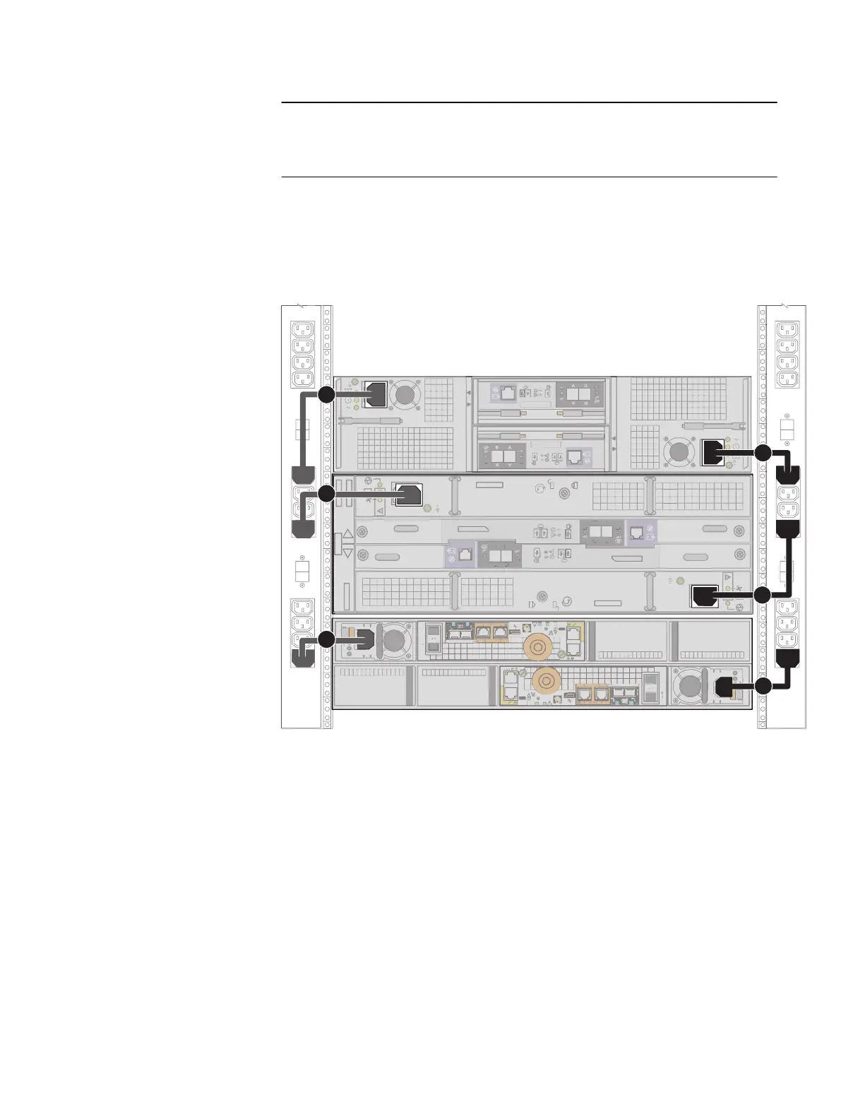
3. For each DPE power cable (shown as cables 1 and 2 in Figure 9 on page 27),
plug the cable into the system component.
The power cable to Power Distribution Unit (PDU) A is black. The power cable
to PDU B is gray.
Figure 9 Power cables to the DPE and optional DAEs
AC
DC
AC
DC
1 GbE
4
5
1
4
5
5
5
A
B
x4 x4
A B
A
B
#
A B
A
B
x4 x4
B
A
0 1
0
1
x4x4
x4
4. Secure each power cable to the system component with the cable retention bail
(moveable metal clip) on the component.
5. Connect the power to the DPE. Plug the free end of the power cables into the
PDU. Connect the power supply for SP A (shown as cable 1 in Figure 9 on page
27) to PDU A . Connect the power supply for SP B (shown as cable 2 in ) to
PDU B.
6. Bundle and secure the cables as necessary with tie wraps.
7. If your storage system has been installed in a cabinet, place the single-sided
adhesive backed Shut Down Procedure label included in the Accessory Kit on
the back of the cabinet door. Otherwise, place this label in a location that is
visible while viewing the storage system from the rear.
8. Monitor the system as it powers up. It takes approximately 10-15 minutes for
the system to power up. The LEDs show the progress of system activation.
Green, blue, and amber activity lights blink during the startup sequence. Review
the next section for information on the power up states.
Cable and power up your storage system components
DPE power up 27