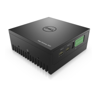
Figure 17. ANT5 and ANT6 antenna holes in back panel and side panel
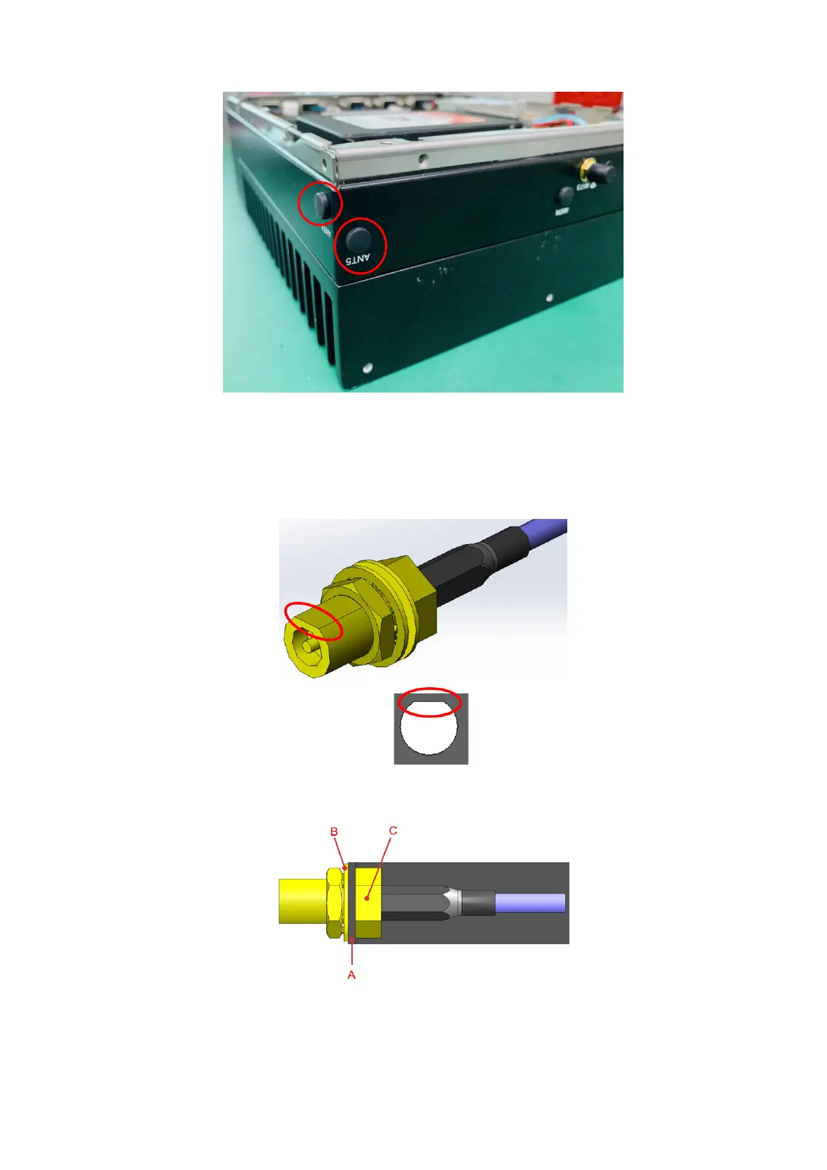
5. Install the SMA cables into the antenna holes in the back and side panels. Align the flat section of the gold connector tube
with the flat section of the antenna hole. Position the SMA cable connector so that the sheet metal of the panel is between
the connector nut and the washer. Use an 8 mm nut driver to torque the SMA cable outer nut to 8 kgf.cm. See the following
figures and tables for cabling details.
Figure 18. Align SMA cable with antenna hole
Figure 19. Position sheet metal (A) between washer (B) and cable connector nut (C)
Installation procedure for 4G expansion module
15