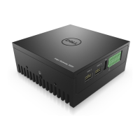
Figure 36. Side panel nuts
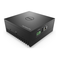
4. Remove the rubber insert from the ANT1, ANT4, ANT5, and ANT6 antenna holes.
Figure 37. ANT1 antenna hole in side panel
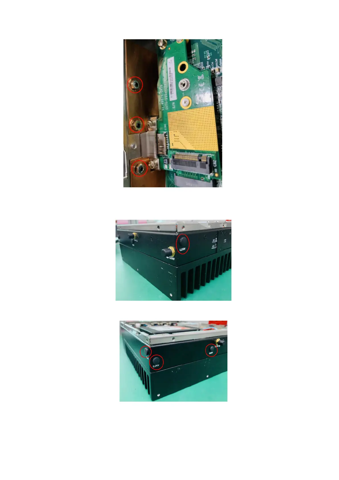
Figure 38. ANT4, ANT5, and ANT6 antenna holes in back panel and side panel
5. Install the SMA cables into the antenna holes in the back and side panels. Align the flat section of the gold connector tube
with the flat section of the antenna hole. Position the SMA cable connector so that the sheet metal of the panel is between
26
Installation procedure for 5G expansion module