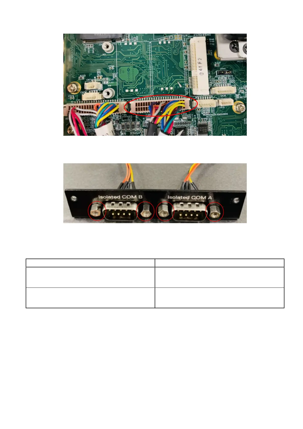
Figure 63. Connect dual-port COM cable to motherboard header
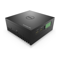
9. Use four H4 standoffs to secure the Isolated COM ports to the Isolated COM I/O panel, as shown in the following figure.
Figure 64. COM ports installed on Isolated COM I/O panel
Use the following table to configure the Isolated COM ports.
Table 15. Isolated COM port mappings
Cable > Port Cable > Port
RS-422 A Label > Isolated COM A
RS-422 B Label > Isolated COM B
RS-422 A Label > Isolated COM A
RS-485 A Label > Isolated COM B
RS-485 A Label > Isolated COM A
RS-485 B Label > Isolated COM B
RS-232 > Isolated COM A
RS-232 > Isolated COM B
10. Secure the Isolated COM I/O panel to the front I/O panel. Use the two screws to the sides of the Isolated COM I/O panel
and the two screws on the bottom edge of the chassis, as shown in the following figure.
Installation procedure for 2x isolated COM 422/485 or 232 uFM module
41