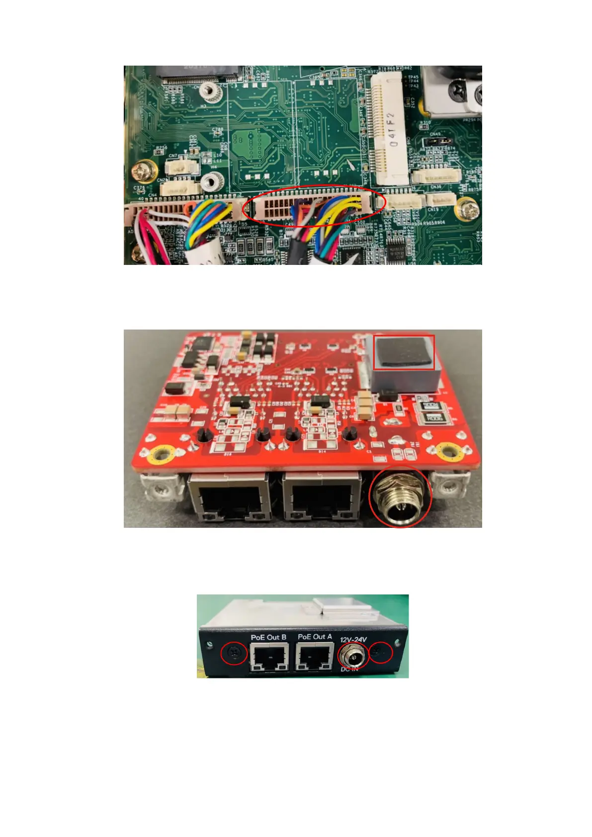
Figure 80. Connect dual-port COM cable to motherboard header
9. Apply the thermal pad to the uFM module, and use a 10 mm nut driver to remove the nut and washer from the DC IN jack, as
shown in the following figure.
Figure 81. Apply thermal pad and remove nut and washer
10. Connect the uFM board to the I/O panel that is included in the Expansion Module, using the two screws and the nut and
washer of the DC IN jack, as shown in the following figures.
Figure 82. GbE with PoE I/O panel
50
Installation procedure for 2x GbE with PoE uFM module