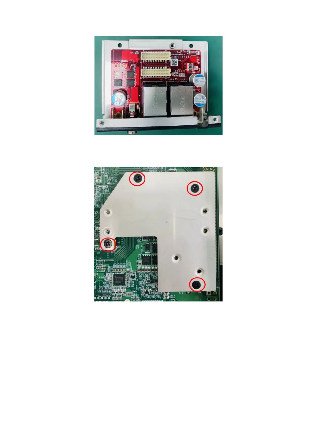
Figure 83. GbE with PoE uFM module with I/O panel
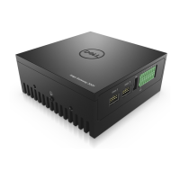
11. Secure the bracket to the motherboard using four screws, as shown in the following figure.
Figure 84. Bracket secured to motherboard
12. Use two M3 x 6L screws to secure the uFM module to the bracket, and secure the GbE with PoE I/O panel to the front I/O
panel, as shown in the following figures.
Installation procedure for 2x GbE with PoE uFM module
51