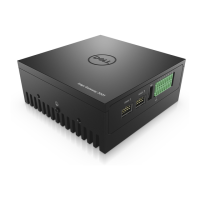
Figure 85. uFM module secured to bracket and chassis
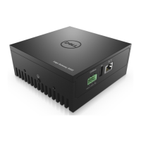
Figure 86. GbE with PoE I/O panel secured to front I/O panel
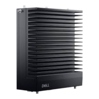
13. Use one M3 x L5 screw to install the cable clip to the bracket, as shown in the following figure.
Figure 87. Cable clip on bracket
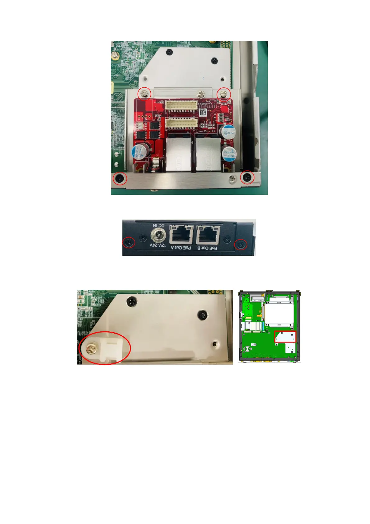
14. Use the two M2.5 x 6L screws to secure the mPCIe LAN board to the motherboard, as shown in the following figure.
52
Installation procedure for 2x GbE with PoE uFM module