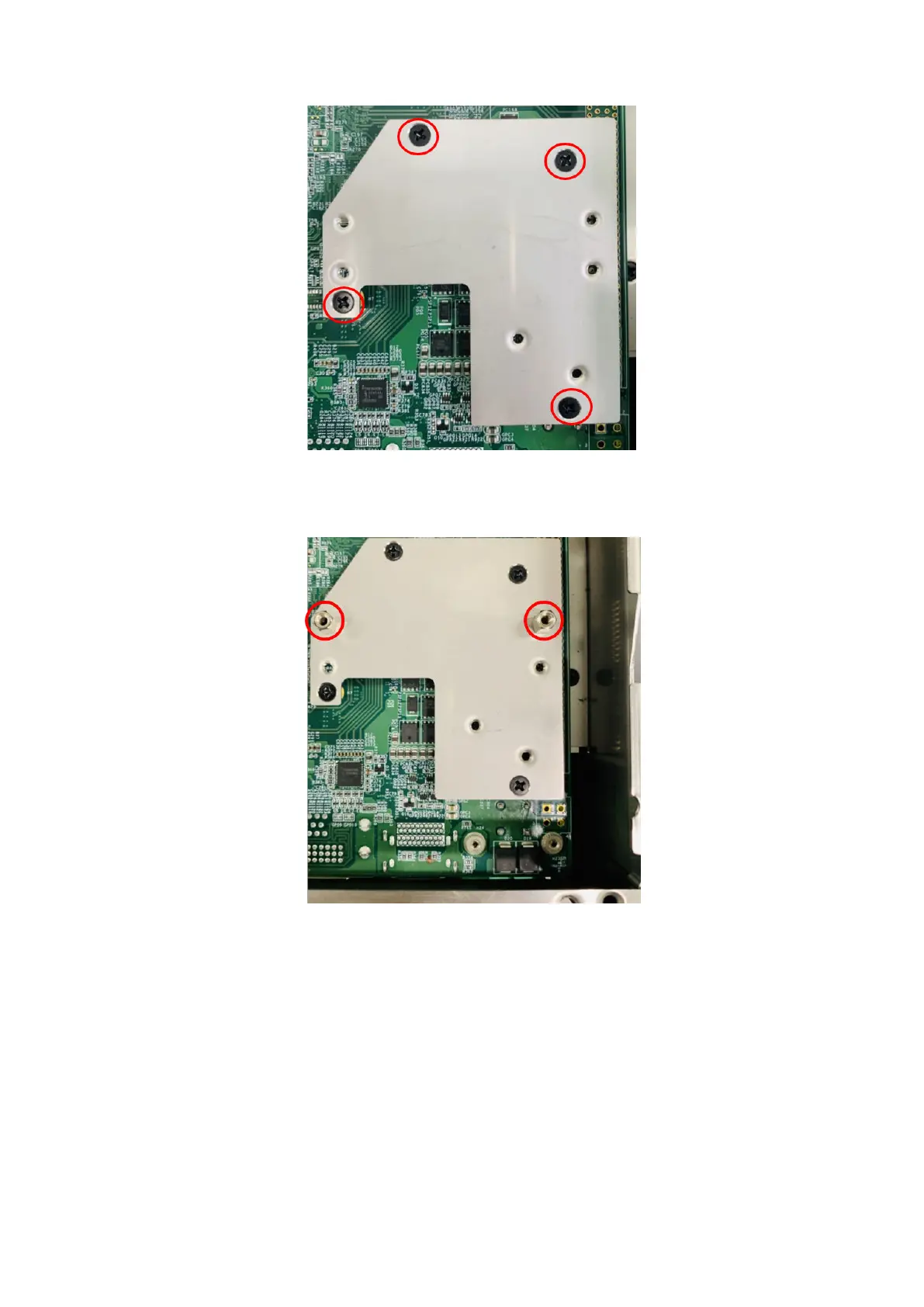
Figure 130. Bracket installed
7. Install two H7 standoffs on the bracket, as shown in the following figure.
Figure 131. Standoffs installed on bracket
8. Secure the DI/O front panel to the main I/O panel. Use the two screws to the sides of the DI/O front panel and the two
screws on the bottom edge of the chassis. Use two M3 x 6L screws to secure the module to the standoffs on the bracket,
as shown in the following figure.
76
Installation procedure for 8x DI/O uFM module