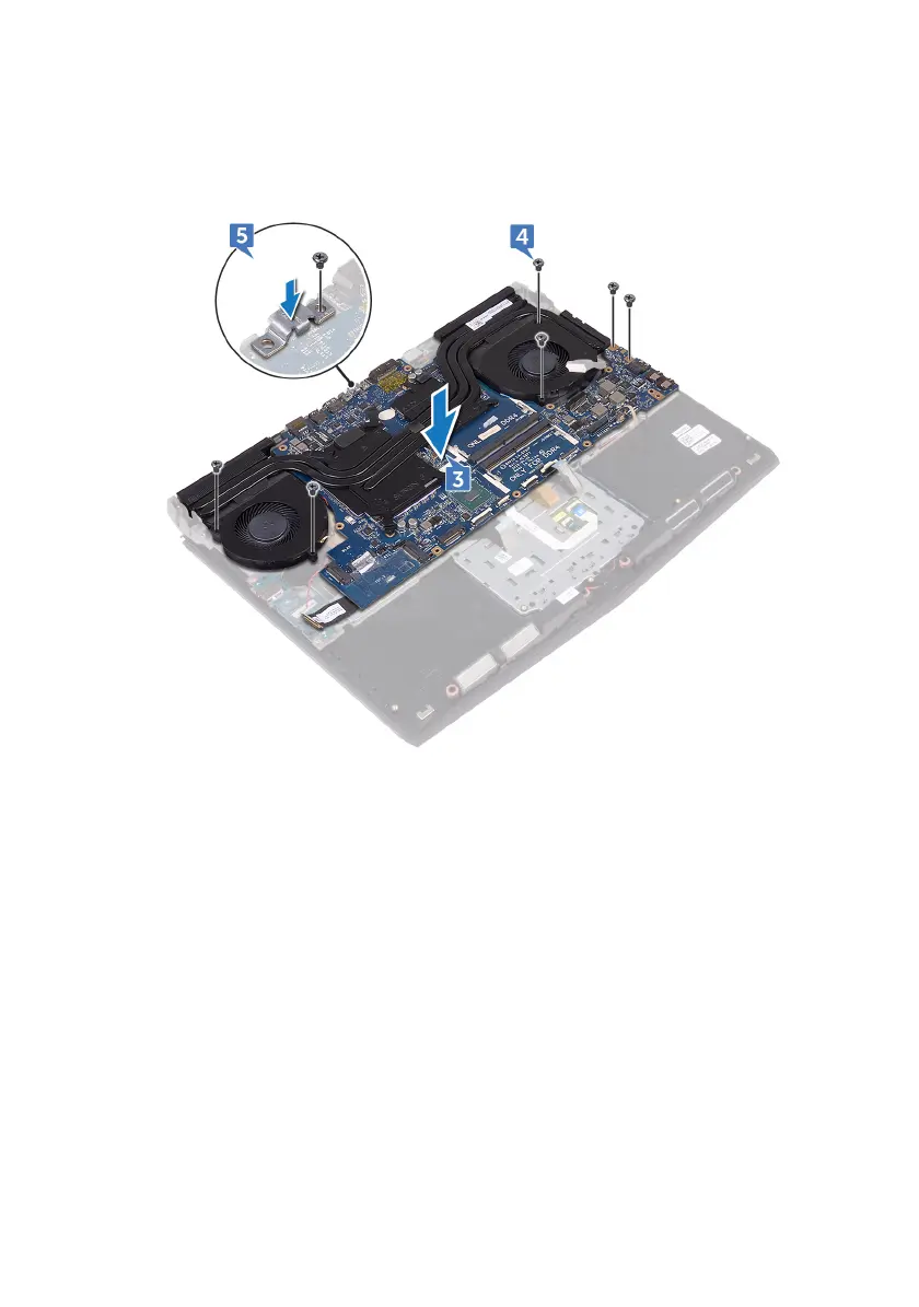
5 Align the screw hole on the USB Type-C port bracket with the screw hole on
the system board and replace the screw (M2.5x5) that secures the USB Type-
C port bracket to the system board.
6 Slide the I/O-board cable into the connector on the I/O-board and close the
latch to secure the cable.
7 Adhere the tape that secures the I/O-board cable to the I/O board.
8 Slide the touchpad cable into the connector on the system board and close
the latch to secure the cable.
9 Connect the speaker cable to the system board.
10 Insert the RGB per key keyboard cable (optional) into the connector and
press down the latch to secure the cable.
11 Connect the power-adapter port cable to the system board.
12 Route the coin-cell battery through the routing channel and adhere the tape
to secure the cable.
79