Service Manual
17
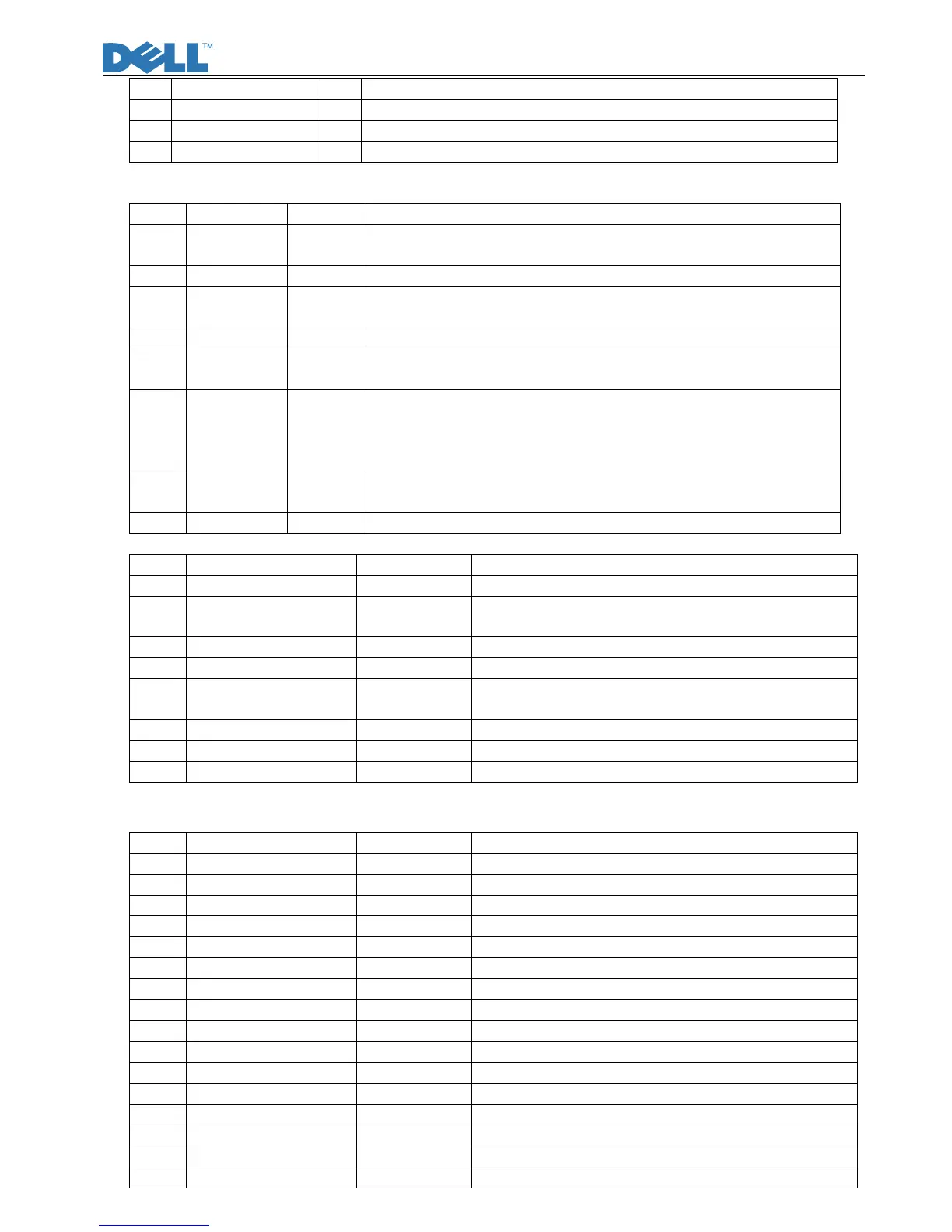
125 GPIO_13 I/O General-purpose input/output 13
126 GPIO_14 I/O General-purpose input/output 14
127 PPWR O Panel power enable
128 AVDD_BIAS_33 P Analog 3.3V supply for LVDS PLL and Bandgap
8.2 U402 (Serial Flash)
Pin Symbol I/O Description
1 CE# I The device is enabled by a high to low transition on CE#. CE#
must remain low for the duration of any command sequence.
2 SO I/O To transfer commands, addresses, or data serially into the device.
3 WP# I/O The write protect (WP#) pin is used to enable/disable BPL bit in
the status register.
4 VSS G Connect ground
5 SI I/O To transfer commands, addresses, or data serially into the device
input are latched on the rising edge of the serial clock.
6 SCK I/O To provide the timing of serial interface.
Commands, addresses, or input data are latched on the rising
edge of the clock input, while output data is shifted out on the
Falling edge of the clock input.
7 HOLD I/O To temporarily stop serial communication with SPI flash
memory without resetting the device.
8 VDD P To provide power supply.
8.3 U850 (LD7575, Power Controller)
Pin Symbol I/O Description
1 RT This pin is to program the switching frequency
2 COMP
I Voltage feedback pin,By connecting a photo-coupler
to close the control loop and achieve the regulation
3 CS I Current sence pin
4 GND
5 OUT
O PWM output ,Gate drive output to drive the external
MOSFET
6 VCC I Power supply
7 NC Unconnected pin
8 HV I PWM output
8.4 U1 ( INL816GN, CCFL Inverter controller IC)
Pin Symbol I/O Description
1 DRV1 O Driver output 1
2 VDDA --- Supply voltage input
3 SEL I Select Signal for Push-Pull or Half-Bridge Topology
4 RT1 I/O Timing Resistor for Striking Frequency
5 RT I/O Timing Resistor for Operation Frequency
6 ENAPWM I Enable and PWM Dimming input
7 PID I Analog Dimming input
8 TIMER I/O Timing Capacitor for Delay Timer
9 ISEN1 I Currentfeedback1
10 ISEN2 I Currentfeedback2
11 VSEN I Voltage Feedback
12 OLP1 I Open-Lamp Protection Sense1
13 OLP2 I Open-Lamp Protection Sense2
14 SSTCMP I/O Soft-Start and Compensation
15 GNDA --- Ground
16 DRV2 O Driver output 2