Service Manual
7
2.2 Power PWM circuit operations
2.2.1) Block diagram:(fig.4)
Fig.4
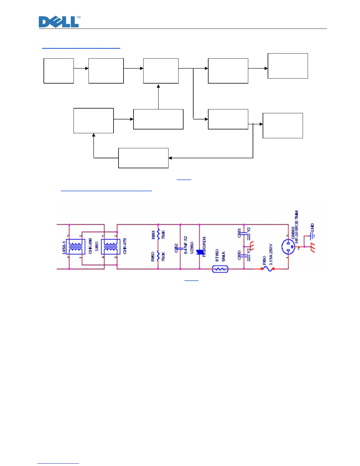
2.2.2) AC Input and EMI Filter:(fig.5)
Fig.5
CN850 is a connector for connecting AC Power. F850 is a fuse to protect all the circuit AC. Input
voltage is from 90V to 264V. R850 and R851 are joined between two inputting main circuit to prevent
man from shock. L850 is used to filter low frequency noise. C850 and C851 are used to discharge the
noise that L850 produced. High frequency waves are damped by C852 .
EMI Filter
Rectifier and
filter
Isolation power
transformer
Rectifier and filter
Inverter circuit
PWM controller
Switching element
Feedback Isolation
Rectifier and filter
To IF connector