Procedure
1. Remove the screw(s) securing the control panel module to the chassis.
2. For a 3.5 inch cabled hard-drive chassis:
a. Remove the screw(s) securing the LED panel to the chassis.
b. Remove the LED panel.
3. Remove all the cables connecting the control panel module to the chassis.
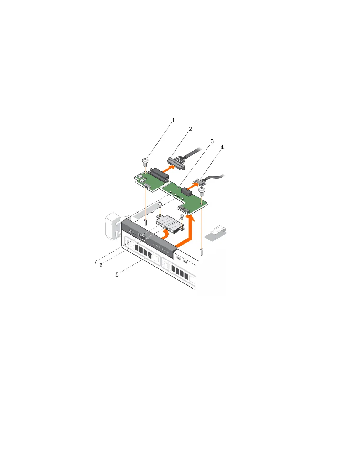
Figure 93 Removing the control panel module—four cabled hard-drive chassis
a. screw (2)
b. control panel module connector cable
c. control panel module
d. USB connector cable
e. control panel
f. LED-panel screw (2)
g. LED panel
Installing and removing system components
176 Dell PowerEdge R430 Owner's Manual

 Loading...


