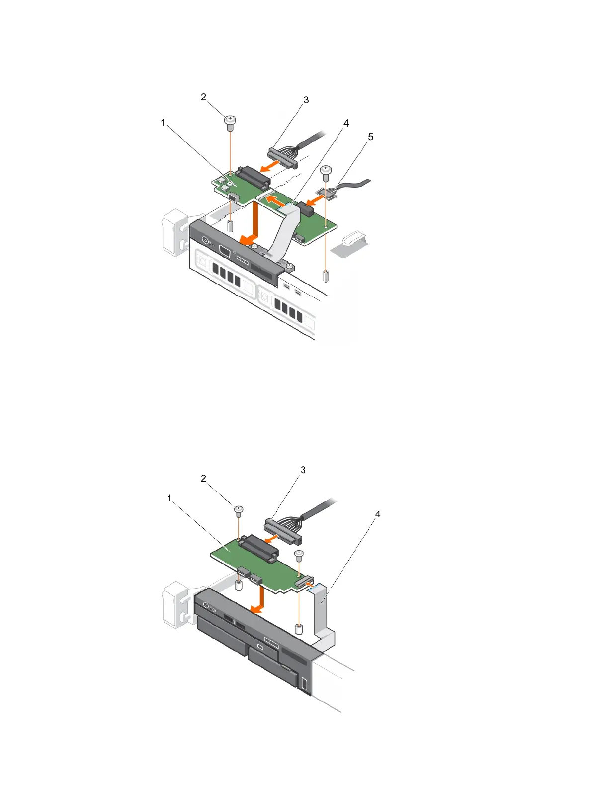
Figure 97 Installing the control panel module—four hard-drive chassis
a. control panel module
b. control panel module screws (2)
c. control panel module connector cable
d. display module cable
e. USB connector cable
Figure 98 Installing the control panel module—eight hard-drive chassis
a. control panel module
Installing and removing system components
180 Dell PowerEdge R430 Owner's Manual

 Loading...


