Features
NOTE: For more information about the display options,
see Display Options.
10 DisplayPort one Connect a monitor or another DisplayPort enabled device.
Provides video and audio output.
NOTE: For more information about the display options,
see Display Options.
11 HDMI port Connect a monitor or another HDMI‑in enabled device.
Provides video and audio output.
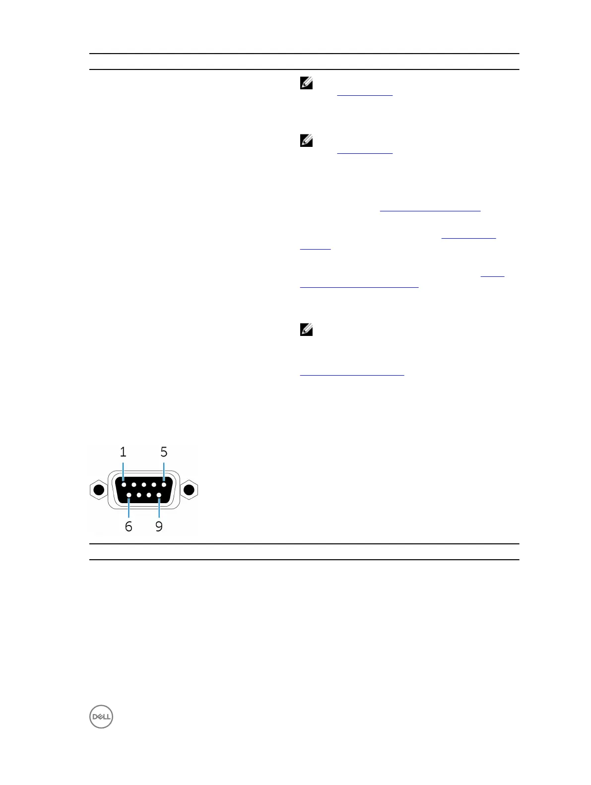
12 CANbus port (optional) Connect to a CANbus port enabled device or dongles. For
more information, see CANbus connector mapping.
13 VGA port Connect a monitor or another VGA enabled device. Provides
video output. For more information, see VGA connector
mapping.
14 12-26V DC power port (barrel connector) Connect a 12-26V DC power cable for supplying power to
your Embedded Box PC. For more information, see 12-26V
DC power port (barrel connector).
15 Audio ports (3) Connect a speaker, a headphone, a microphone, or a
headset (headphone and microphone combo).
NOTE: Connect the headset to the Line Out port.
16 +12-26V DC power connector Connect a 12-26V DC power connector for supplying power
to your Embedded Box PC. For more information, see
+12-26V DC power connector.
1 Connections made to these ports must use SELV circuits and the wire (26 AWG-18 AWG) must have Double Insulation (DI) or Reinforced Insulation (RI) to
protect it from all hazardous voltages. Torque the screws at 2.88 kg-cm (2.5 lb-in) to secure the wire to the connector.
CANbus connector mapping
Pin Signal Pin Signal
1 NC 6 NC
2 CAN_L 7 CAN_H
3 GND 8 NC
4 NC 9 NC
5 NC
7
 Loading...