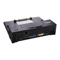
Table 4. Back panel features and indicators
Item Indicator, button, or connector Icon Description
1 Serial connector Enables you to connect a serial device to the system.
2 vFlash card slot (optional) Enables you to connect the vFlash card.
3 iDRAC port (optional) Enables you to install a dedicated management port card.
4 PCIe expansion card slots (2) Enables you to connect PCI Express expansion cards.
5 Power supply unit (PSU1 and
PSU2)
Enables you to install up to two 350 W redundant AC power supply
units.
6 USB connectors Enables you to connect USB devices to the system. These ports are
USB 3.0-compliant.
7 Ethernet connectors Enables you to connect Integrated 10/100/1000 Mbps NIC
connectors.
8 System identication button Enables you to locate a particular system within a rack. The
identication buttons are on the front and back panels. When one
of these buttons is pressed, the LCD panel on the front and the
system status indicator on the back ash until one of the buttons is
pressed again.
Press the system identication button to turn the system ID on or
o.
If the system stops responding during POST, press and hold the
system ID button for more than ve seconds to enter BIOS
progress mode.
To reset iDRAC (if not disabled in F2 iDRAC setup), press and hold
the button for more than 15 seconds.
9 System identication connector Connects the optional system status indicator assembly through
the optional cable management arm.
10 Video connector Enables you to connect a VGA display to the system.
About your system 11
 Loading...