Cable routing
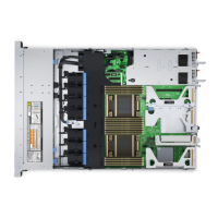
Figure 45. Control panels and intrusion switch
Table 17. Control panels, BOSS S2 and VGA cabling
From To
Left control panel connector Left control panel (LCP)
Right control panel connector Right control panel (RCP)
Front VGA connector VGA on RCP
BOSS_CARD_PWR (BOSS S2 module power connector on
system board)
BOSS_PWR (BOSS S2 module power connector on BOSS S2
module)
SL6_PCH_PA4 (BOSS signal connector on system board) BOSS signal on BOSS S2 card module
56 Installing and removing system components
 Loading...

