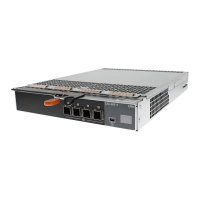
Item Indicator, Button, or
Connector
Icon Description
1,2,3,4 SAS port (Input or
Output)
Provides SAS connections for cabling the host or an upchain expansion enclosure
and to the next down chain expansion enclosure in a daisy chain.(Single Port,
Redundant, and Multi-chain Configuration)
5 USB Mini-B (serial
debug port)
For engineering use only.
6 7-Segment Display Display the enclosure location in SAS Chain.
Enclosure failover when two EMMs are installed
If two EMMs are installed, a certain degree of failover is offered. Control and monitoring of the enclosure elements can be transferred
from one EMM to another in the event of an EMM failure. A failover occurs whenever network communication is ended between an EMM
and its peer.
In the event of a peer EMM failure, the surviving EMM activates the amber status LED of the failed EMM. The surviving EMM then takes
over the responsibility of enclosure management, which includes monitoring and control of the enclosure LEDs, power supply units, and
fans.
EMM thermal shutdown
If critical internal temperatures are reached, the enclosure turns off automatically through either a thermal shutdown command issued by
the EMM firmware or through a command from Dell OpenManage Server Administrator.
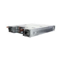
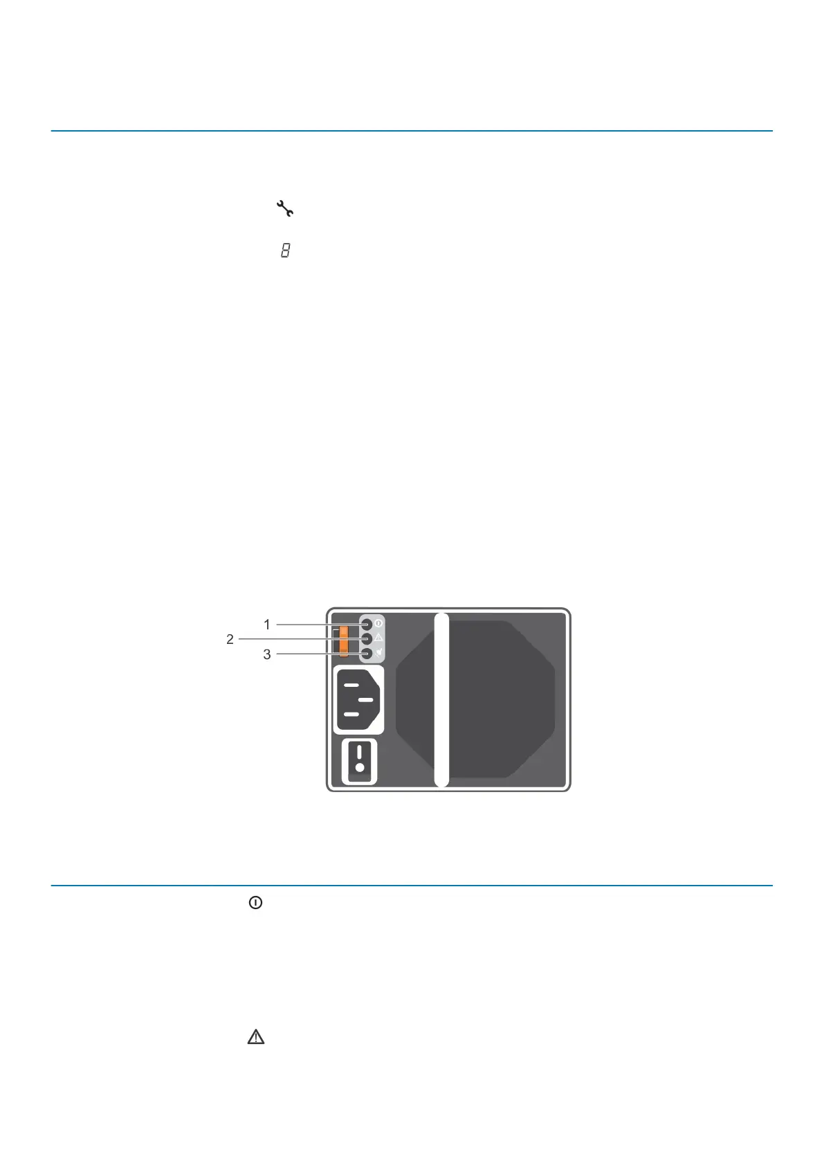
Power indicator codes
Figure 6. Power indicator codes
Item
LED
Icon
Color State
1 DC power Green
• ON — Normal operation. Power supply is connected to DC power
and the power switch is on. The power supply module is supplying DC
power to the array.
• OFF — Indicates any one of the following:
• The power switch is off.
• The power supply module is not connected to power.
• There is a fault condition.
2 Power supply
module fault
Yellow
• ON — Fault detected.
About your enclosure 9
 Loading...