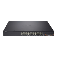
10 Hardware Overview
System LEDs
The system contains light emitting diodes (LEDs) that provide indications
about the System, Temp, Diag, Fan, Stack, and Locator status of the Dell
Networking N4000 switch. Table 1 contains the status LED definitions:
Table 1. LED Definitions for System
Feature Detailed Description Comment
System LED
• Solid blue - Normal
operation
• Blinking blue - Booting
• Solid red - Critical
system error
• Blinking red - Non-
critical system error (fan
fail, power supply fail)
On front panel
Temp LED
•Off - Normal
temperature
• Solid red - Overtemp
a
On back panel
Diag LED
• Off - Normal operating
• Blinking green -
Diagnostic test running
On back panel
Fan LED
• Solid green - Fan
powered and at expected
RPM
• Solid red - Fan failed
On back panel
Stack LED
• Solid blue - Switch in
stacking master mode
• Solid green - Switch in
stacking slave mode
• Off - Switch in stand
alone mode
On back panel
 Loading...