25 Stacking Dell Networking Switches: N4032, N4032F, N4064, N4064F
Note: Ring topologies are highly recommended for resiliency and fault tolerance over the daisy-chain.
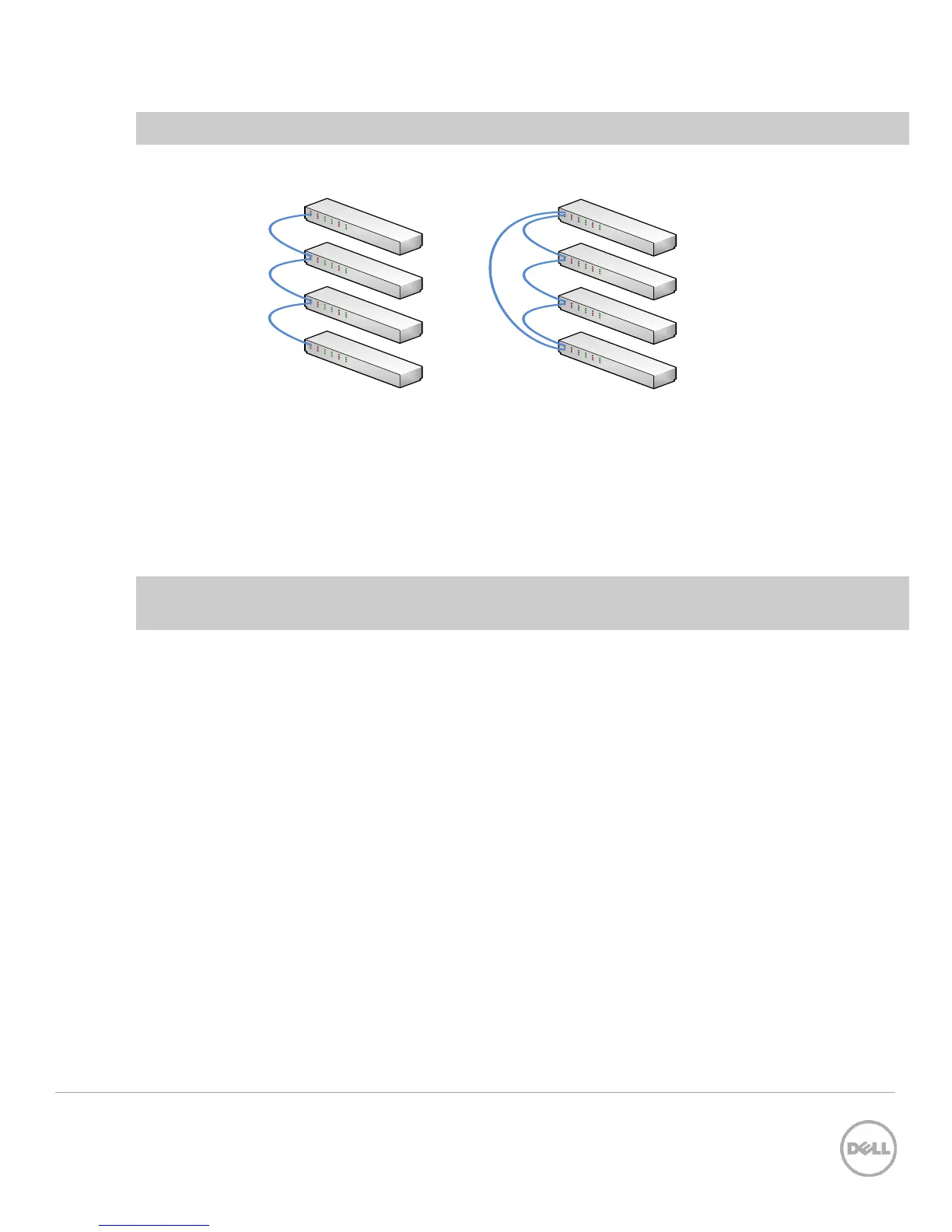
Daisy Chain topology
Ring (loop) topology
On a
daisy-chain
stack:
1. Configure the existing stack with new stack ports to be used to connect to the new switch.
2. Cable the new switch to one of the end units of the existing stack.
3. Power up the new switch. The switch will be added to the stack.
Note: While there are fewer steps in a daisy-chain topology, the ring topology is highly recommended
for its resiliency and fault tolerance over the daisy-chain.
On a
ring topology
stack:
1. Plug new cables into
half
of the stack ports configured on the new switch to be added.
2. Unplug the stacking cables from any existing member going to another existing member in the
stack. Only unplug the cables from one end, leaving them plugged into the other member.
3. Note: Only half of the stack cables in this member will be unplugged. The cables going in the
other direction to a third existing member will not be removed.
4. Plug the other end of the new cables of the switch being added into the stack ports that were
unplugged in step 2.
5. Plug the remaining cable ends (removed in step 2) into the remaining stack ports configured on
the new switch unit.
6. Power up the new switch. The switch will be added to the stack. Allow a few minutes for the new
switch to boot up completely.
2.3.1.2 Validation
After the entire stack is created, it can be validated with the show switch command from the Master
switch:
console#show switch
Management Standby Preconfig Plugged-in Switch Code