40 Stacking Dell Networking Switches: N4032, N4032F, N4064, N4064F
associated with these interfaces. Use the locate switch command to blink the blue “Locator” LED on
the switch unit you are trying to locate.
console#locate switch 2
The blue LED locator light on switch 2 blinks for 20 seconds. The length of time the LED continues to
blink can be changed using the locate time <ssss> command, where
ssss
is the time in seconds for
the LED to blink.
2.5.1.1 Removing the physical switch unit from the stack
Before removing a physical unit from a stack, prepare ports on the other stack member units to receive
the cables and traffic that is redirected to them from the member unit being removed. Consider all LAGs,
VLANs, STP, ACLs, security, and so on, that needs to be configured on the new ports to accept cables,
establish links, and begin to forward traffic.
Note: It is highly recommended not to continue until these things have been considered and proper
preparations are made.
Note: Do not remove or re-route stacking cables until prompted in the last step below.
Do not remove or re-route
stacking
cables until prompted. Disconnect all other links on the member to
be removed and re-route the traffic that was going through this unit so it now goes through the ports that
were prepared on the remaining stack unit members.
Caution: In the next step, make sure to keep track of all ports being used for stacking that will be
temporarily unplugged. They need to be re-cabled in the following step.
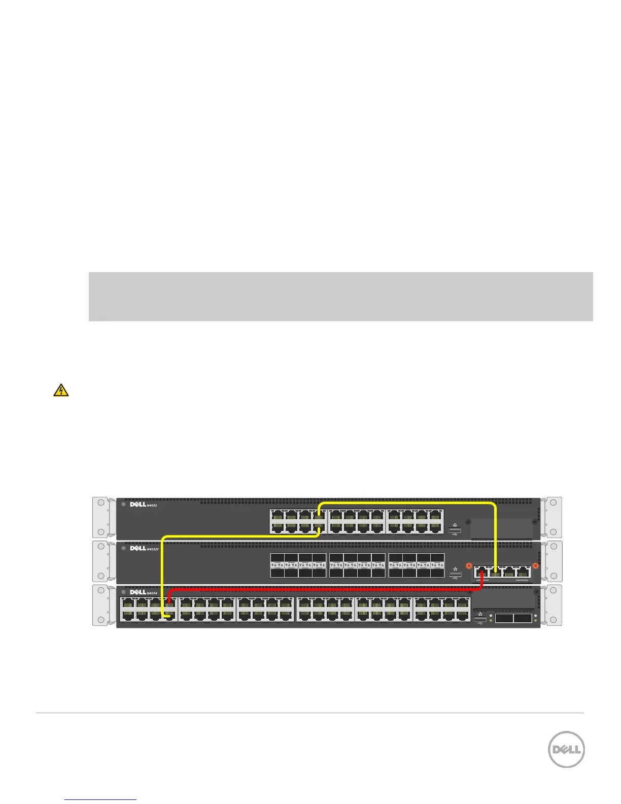
Only after re-routing the traffic through the remaining stack units, remove the stacking cables from the
switch to be removed. The switch being removed does not need to be powered off. Keeping the
switches power on automatically brings it to a stand-along state as the stack cables are removed. In the
example below (Figure 13), the red cable is removed along with the switch.
19 21 23
20 22 24
17
18
11 13 15
12 14 16
9
10
3 5 7
4 6 8
1
2
ACTLNK
2 864
1 753
10 161412
9 151311
18 242220
17 232119 ACTLNK
ACT
LNK
ACT
LNK
7 9 151311 17 232119 25 312927 33 393735 41 474543 ACTLNK
1 2
2 864 10 161412 18 242220 26 323028 34 403836 42 484644
SWITCH TO BE REMOVED
FROM STACK
Cabling of three stacked units Figure 13