10. SATA3 connector (white)
11. SATA power cable connector
12. M.2 WLAN connector
13. System power connector
14. Internal speaker connector
15. Coin-cell battery
16. Thunderbolt header
17. PCIe x4 (Slot4)
18. PCI (Slot3)
19. PCIe x16 (Slot2)
20. PCIe x1 (Slot1)
21. System fan connector
22. Chassis Intrusion Detection connector
23. Type-C connector
24. Processor socket
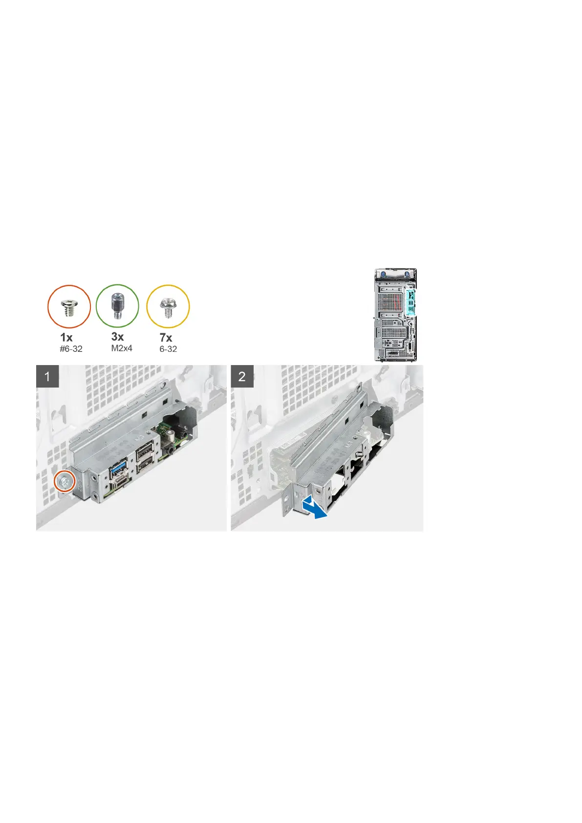
The following images indicate the location of the system board and provide a visual representation of the removal procedure.
Removing and installing components 95