Table 16. Connector descriptions for 10 x 2.5-inch drive backplane to the onboard controller (6:4 NVMe)
From To
BP_PWR_1 (backplane power connector) SIG_PWR_1 (system board power connector)
DST_PA1 (backplane SATA connector, cable marking BP PA1) SL3_CPU1_PB2 (signal connector on the system board, cable
marking MB SL3)
SYS_PWR2 (system board power connector) CPU_PWR2 (PSU power connector)
DST_PB1 (backplane SATA connector, cable marking BP PB1) SL4_CPU1_PA2 (signal connector on the system board, cable
marking MB SL4)
DST_PA2 (backplane SATA connector, cable marking BP PA2) SL7_CPU1_PA4 (signal connector on the system board, cable
marking MB SL7)
DST_PB2 (backplane SATA connector, cable marking BP
PB2)
SL2_CPU2_PA1 (signal connector on the system board, cable
marking MB SL2)
DST_PA3 (backplane SATA connector, cable marking BP PA3) SL1_CPU2_PB1 (signal connector on the system board, cable
marking MB SL1)
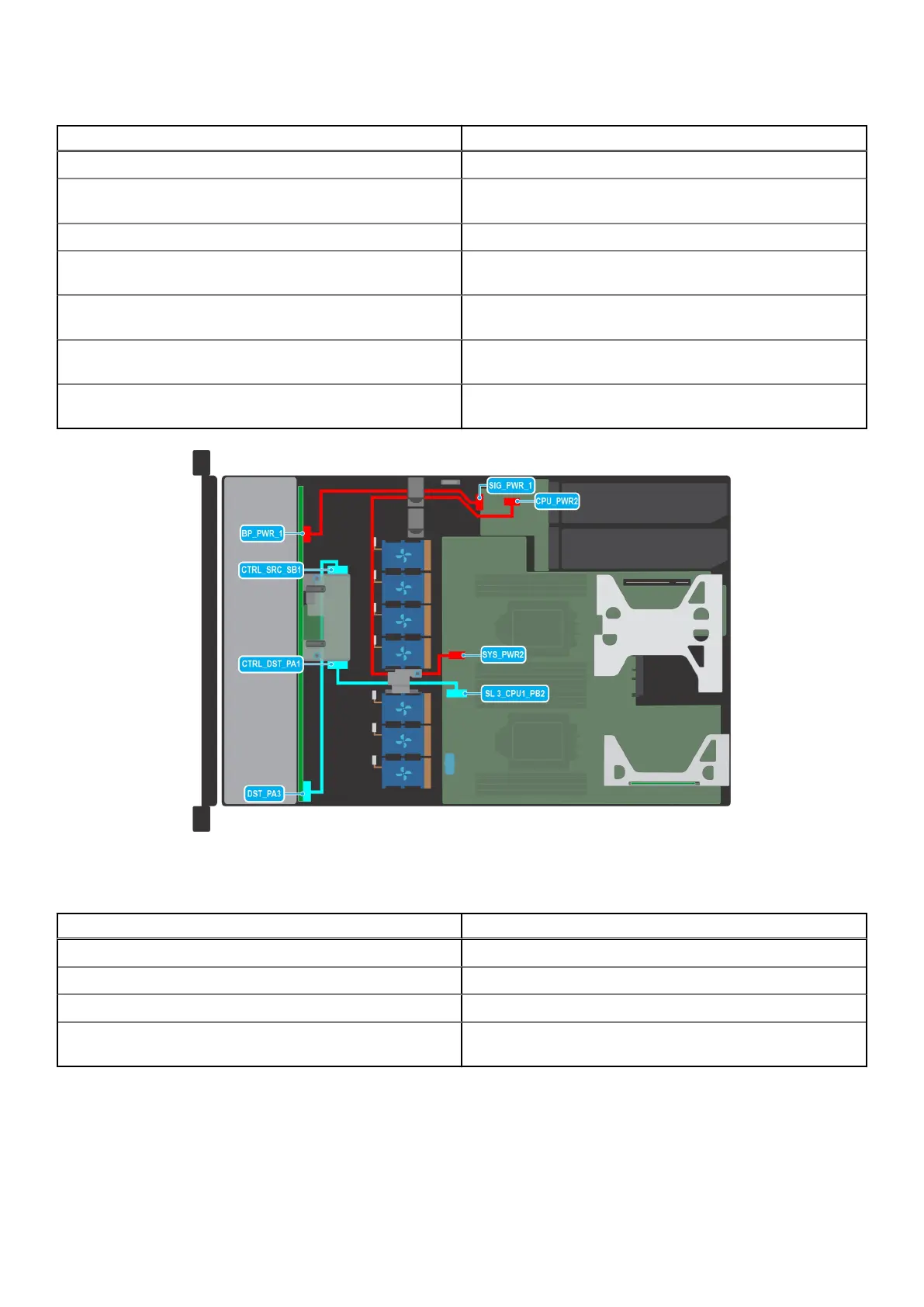
Figure 39. Cable routing - 10 x 2.5-inch drive backplane with Butterfly riser and fPERC
Table 17. Connector descriptions for 10 x 2.5-inch drive backplane with Butterfly riser and fPERC
From To
BP_PWR_1 (backplane power connector) SIG_PWR_1 (system board power connector)
SYS_PWR2 (system board power connector) CPU_PWR2 (PSU power connector)
DST_PA3 (backplane SATA connector, cable marking BP PA3) CTRL_SRC_SB1 (fPERC connector on the backplane)
CTRL_DST_PA1 (fPERC connector on the backplane) SL3_CPU1_PB2 (signal connector on the system board, cable
marking MB SL3)
Installing and removing system components 51
 Loading...