EasyManua.ls Logo

Dell PowerFlex Custom Node R6525 User Manual

Dell PowerFlex Custom Node R6525
51 pages
To Next Page IconTo Next Page
To Previous Page IconTo Previous Page
Page #8 background image
Table 2. Features available on the front of the system (continued)
Item Ports, panels, and
slots
Icon Description
5 Information tag
The Information tag is a slide-out label panel that contains
system information such as Service Tag, NIC, MAC address,
and so on. If you have opted for the secure default access
to iDRAC, the Information tag also contains the iDRAC secure
default password.
Right control panel view
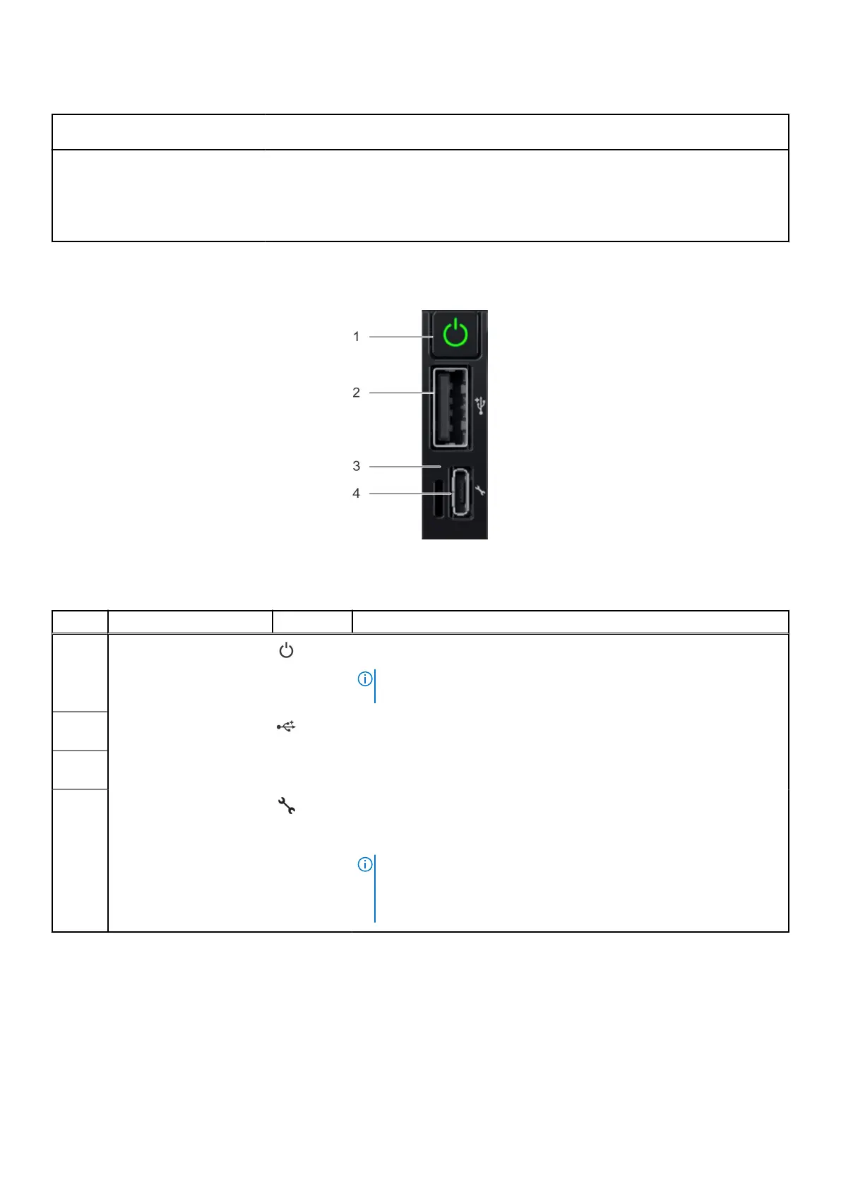
Figure 3. Right control panel
Table 3. Right control panel
Item Indicator or button Icon Description
1 Power button Indicates if the system is powered on or off. Press the power button to
manually power on or off the system.
NOTE: Press the power button to gracefully shut down the ACPI-
compliant operating system.
2
USB 2.0-compliant port The USB port is a 4-pin connector and 2.0-compliant. This port enables
you to connect USB devices to the system.
3
iDRAC Direct LED
indicator
N/A The iDRAC Direct LED indicator lights up to indicate that the iDRAC Direct
port is actively connected to a device.
4
iDRAC Direct port (Micro-
AB USB)
The iDRAC Direct port (Micro-AB USB) enables you to access
the iDRAC Direct Micro-AB features. For more information, see the
Integrated Dell Remote Access Controller User's Guide available at
https://www.dell.com/idracmanuals .
NOTE: You can configure iDRAC Direct by using a USB to micro USB
(type AB) cable, which you can connect to your laptop or tablet. Cable
length should not exceed 3 feet (0.91 meters). Performance could be
affected by cable quality.
8 System overview
Question and Answer IconNeed help?

Do you have a question about the Dell PowerFlex Custom Node R6525 and is the answer not in the manual?

Dell PowerFlex Custom Node R6525 Specifications

General IconGeneral
ProcessorUp to 2x AMD EPYC 7002/7003 series processors, up to 64 cores per processor
Memory32 DDR4 DIMM slots
Drive BaysUp to 24 x 2.5" SAS/SATA (HDD/SSD)
RAID SupportPERC H745P
Networking1GbE, 10GbE, 25GbE
Power Supply1100W Platinum

Summary

About this guide

System overview

Front view of the system

Describes the front panel components and ports of the server.

Right control panel view

Details the buttons and indicators on the right control panel.

Left control panel view

Explains the indicators on the left control panel.

Rear view of the system

Illustrates and describes rear panel ports and connectors.

Inside the system

Shows the internal components and their locations.

Locating the Express Service Code and Service Tag

Explains how to find system identification information.

System information label

Describes the location of the system information label.

Rail sizing and rack compatibility matrix

Provides information on compatible rail kits and rack mounting.

Component installation guidelines

Cable routing

Illustrates cable management for different backplane configurations.

Drive backplane

Lists supported drive backplane options for the system.

Expansion card installation guidelines

Details supported expansion cards and their slot priorities.

Supported GPU cards

Lists compatible GPU cards and their specifications.

System memory

Covers memory types, channels, and population guidelines.

Memory interleaving with Non-uniform memory access (NUMA)

Explains NUMA concepts and configuration.

Memory interleaving population rules

Details rules for optimal memory population and interleaving.

Upgrade kits

BOSS S2 kit

Describes the BOSS S2 kit components and installation.

PCIe Gen 4 NVMe enablement Kit

Details the components for the PCIe Gen 4 NVMe enablement kit.

Serial COM port kit

Lists components for the serial COM port kit.

Jumpers and connectors

System board connectors

Identifies and describes system board connectors.

System board jumper settings

Explains jumper settings for BIOS configuration.

Disabling a forgotten password

Provides steps to clear system and setup passwords.

System diagnostics and indicator codes

Status LED indicators

Describes front panel status LED meanings and corrective actions.

System health and system ID indicator codes

Explains system health and ID indicator status.

iDRAC Quick Sync 2 indicator codes

Details the indicators for the iDRAC Quick Sync 2 feature.

iDRAC Direct LED indicator codes

Describes the LED codes for iDRAC Direct port activity.

LCD panel

Explains the LCD panel features and error reporting.

NIC indicator codes

Describes link and activity LED indicators for network interfaces.

Power supply unit indicator codes

Explains the status indicators for AC and DC power supply units.

Drive indicator codes

Describes the status and activity indicators for drives.

Using system diagnostics

Guides on running system diagnostics for troubleshooting.

System diagnostic controls

Lists controls available in the system diagnostic utility.

Getting help

Recycling or End-of-Life service information

Provides information on product recycling services.

Contacting Dell

Details methods for contacting Dell support.

Accessing system information by using QRL

Explains how to use the Quick Resource Locator.

Receiving automated support with SupportAssist

Describes automated support features with SupportAssist.

Documentation resources

Setting up your system

Lists resources for system installation and rack mounting.

Configuring your system

Provides links to documentation for iDRAC and system configuration.

Managing your system

Lists resources for system management software and drivers.

Troubleshooting your system

Points to guides for identifying and resolving system issues.

Related product manuals