Table 7. Supported backplane options (continued)
System Supported drive options
2.5-inch (x10) SAS, SATA or NVMe backplane
2.5-inch (x2) SAS/SATA/NVME rear backplane
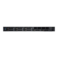
Figure 19. 8 x 2.5-inch drive backplane
1. BP_PWR_1 (backplane power and signal cable to system board)
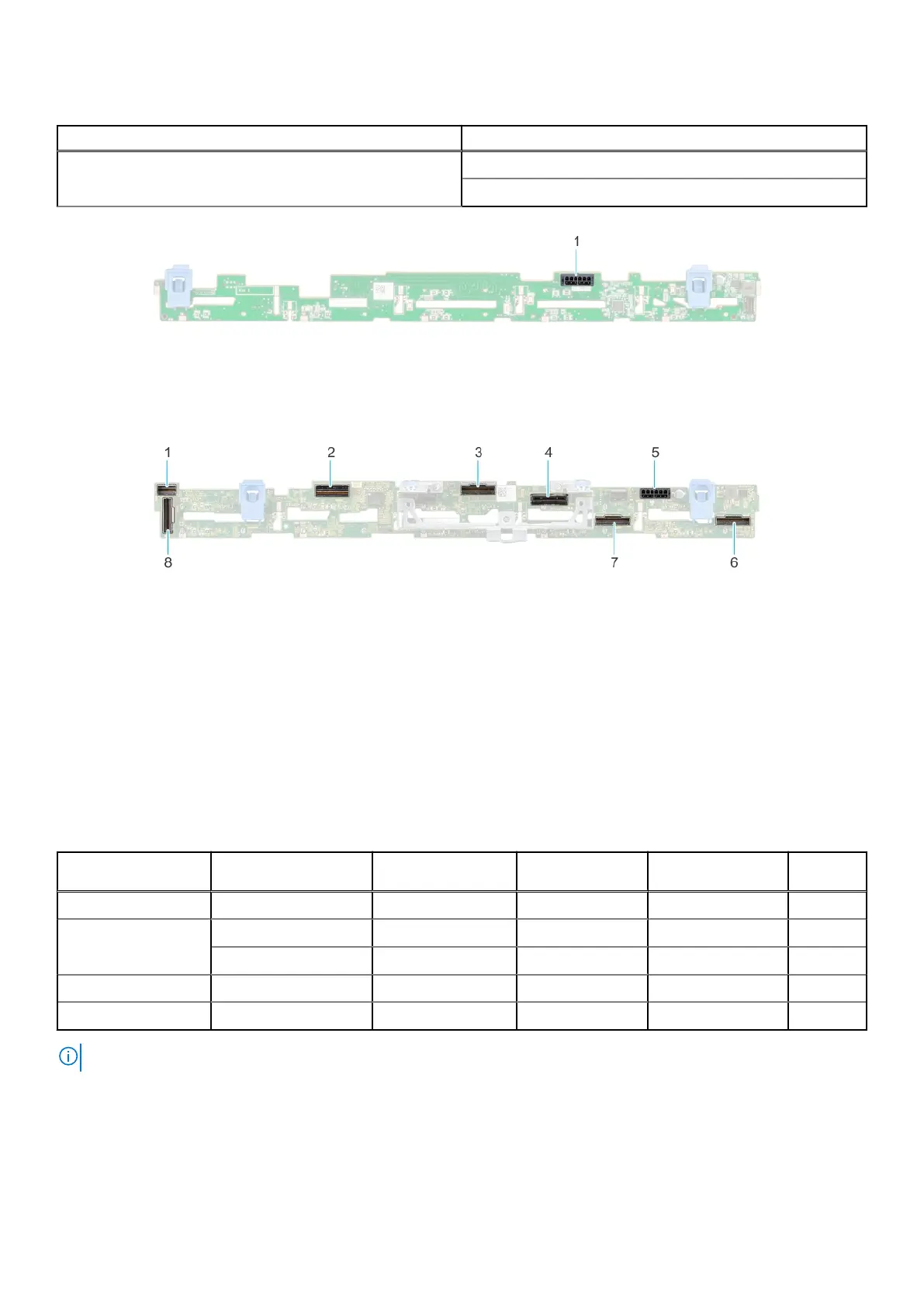
Figure 20. 10 x 2.5-inch drive backplane
1.
DST_SA2 (backplane to front PERC) 2. DST_PB2 (PCIe/NVMe connector)
3. DST_PA2 (PCIe/NVMe connector) 4. DST_SA1 (PERC to backplane)
5. BP_PWR_1 (backplane power and signal cable to system
board)
6. DST_PA1 (PCIe/NVMe connector)
7. DST_PB1 (PCIe/NVMe connector) 8. DST_PA3 (PCIe/NVMe connector)
Expansion card installation guidelines
The following table describes the supported expansion cards:
Table 8. Expansion card riser configurations
Expansion card riser PCIe slots on the
riser
Processor
connection
Height Length Slot
width
R1a (Riser 1) Slot 1 Processor 1 Full Height 3/4th Length x16
R2a (Riser 2) Slot 1 Processor 1 Low Profile Half Length x16
Slot 2 Processor 2 Low Profile Half Length x16
R3a (Riser 3) Slot 3 Processor 2 Low Profile Half Length x16
R4c + R4d (Riser 4) Slot 2 Processor 2 Full Height 3/4th Length x16
NOTE: The expansion-card slots are not hot-swappable.
The following table provides guidelines for installing expansion cards to ensure proper cooling and mechanical fit. The expansion
cards with the highest priority should be installed first using the slot priority indicated. All the other expansion cards should be
installed in the card priority and slot priority order.
20
Component installation guidelines