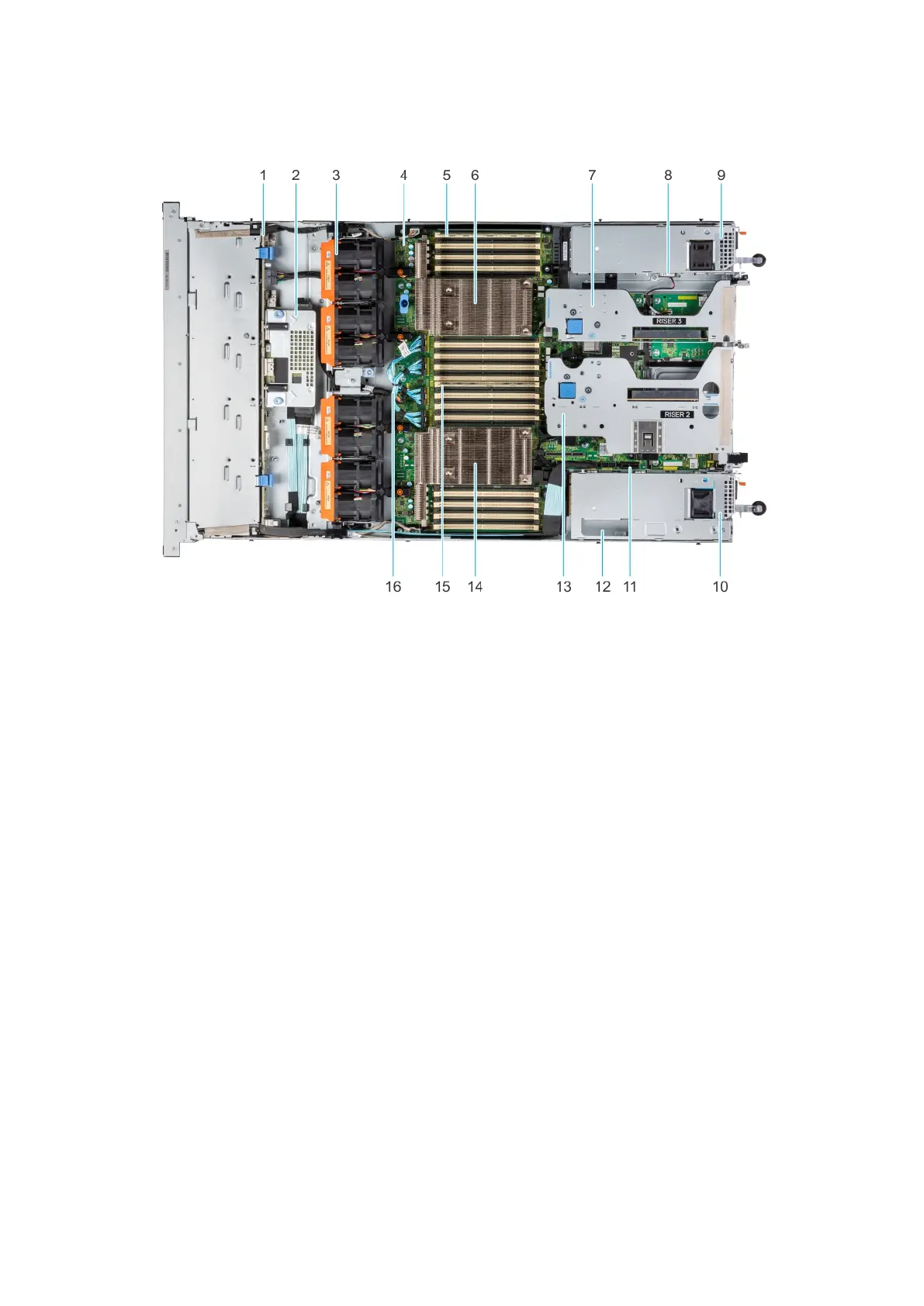
EasyManuals Logo

Dell PowerFlex Custom Node R6525 User Manual

Dell PowerFlex Custom Node R6525
51 pages
To Next Page IconTo Next Page
To Previous Page IconTo Previous Page
Page #12 background imageLoading...
Page #12 background image
Inside the system
Figure 8. Inside the system
1.
Drive backplane 2. Rear mounting front PERC module
3. Dual fan module (4) 4. System board
5. Memory DIMM socket for processor 2 (B1) 6. Heat sink for processor 2
7. Riser 3 8. Intrusion switch
9. Power supply unit (PSU 2) 10. Power supply unit (PSU 1)
11. IDSDM/Internal USB card port 12. BOSS slot
13. Riser 2 14. Heat sink for processor 1
15. Memory DIMM socket for processor 1 (A1) 16. xGMI cables
Locating the Express Service Code and Service Tag
The unique Express Service Code and Service Tag are used to identify the system.
System information label
The system information label is located on the back side of the system cover.
12
System overview

Questions and Answers:

Question and Answer IconNeed help?

Do you have a question about the Dell PowerFlex Custom Node R6525 and is the answer not in the manual?

Dell PowerFlex Custom Node R6525 Specifications

General IconGeneral
ProcessorUp to 2x AMD EPYC 7002/7003 series processors, up to 64 cores per processor
Memory32 DDR4 DIMM slots
Drive BaysUp to 24 x 2.5" SAS/SATA (HDD/SSD)
RAID SupportPERC H745P
Networking1GbE, 10GbE, 25GbE
Power Supply1100W Platinum

Related product manuals