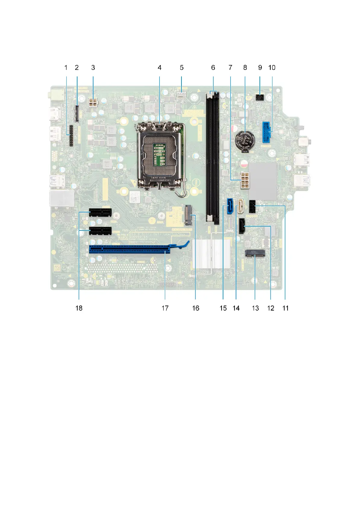
Figure 48. System board callout
1. Serial port connector
2. VGA port connector
3. processor-power cable connector
4. Processor socket
5. processor-fan cable connector
6. memory-module slots
7. system-board power cable connector
8. coin-cell battery socket
9. power-button cable connector
10. media-card reader cable connector
11. Hard drive power cable connector
12. optical-drive data cable connector (SATA 3)
13. M.2 2230 wireless-card slot
14. Hard drive data cable connector (SATA 1)
76
Removing and installing Field Replaceable Units (FRUs)
 Loading...