Steps
1. Remove the two screws (M3x5) that secure the power-supply cable connector bracket to the display-assembly base.
2. Lift the power-supply cable connector bracket off the display-assembly base.
3. Remove the two screws (M3x5) that secure the I/O bracket to the display-assembly base.
4. Lift the I/O bracket off the display-assembly base.
Installing the I/O bracket
Prerequisites
If you are replacing a component, remove the existing component before performing the installation process.
About this task
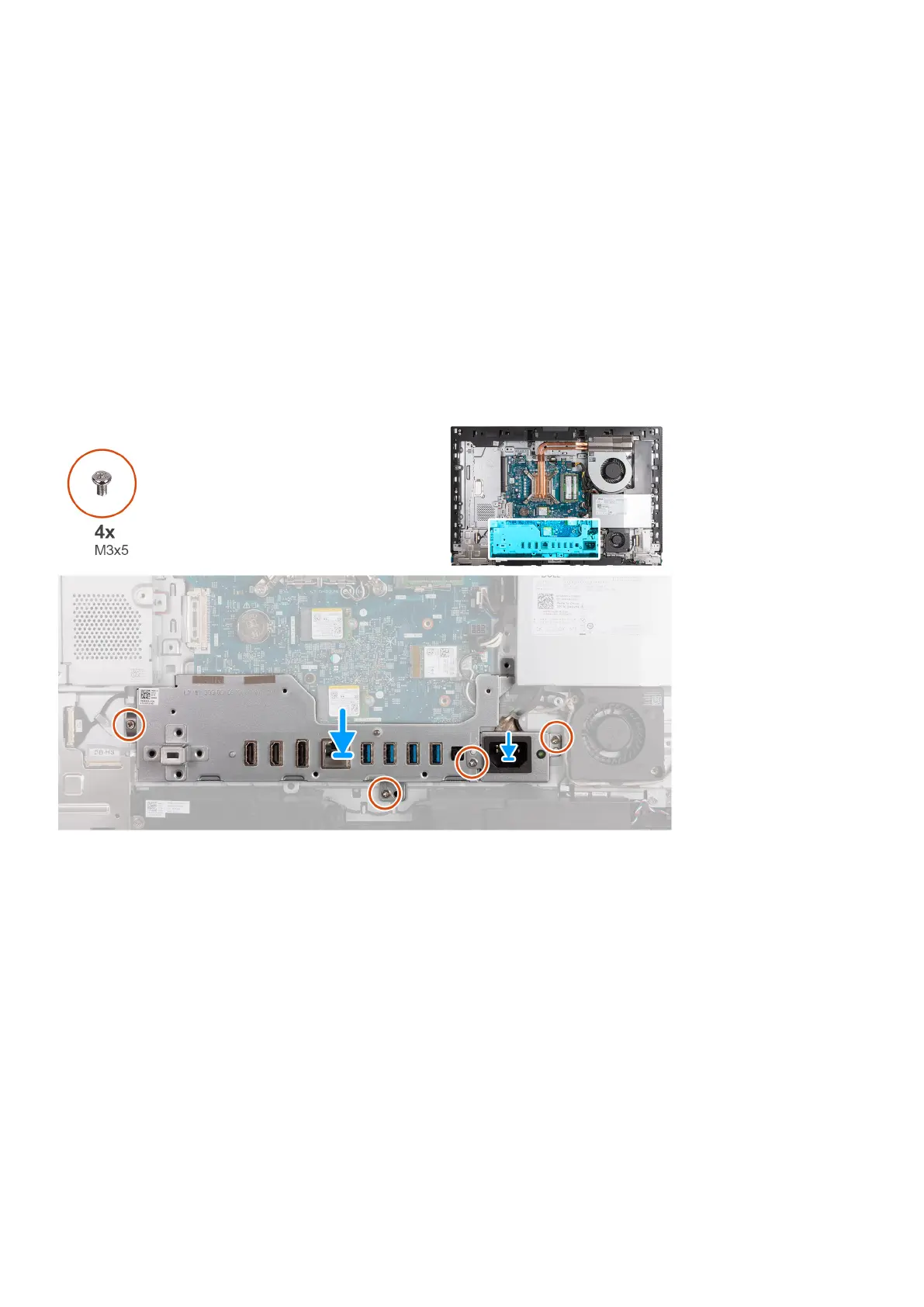
The following image(s) indicate the location of the I/O bracket and provides a visual representation of the installation
procedure.
Steps
1. Place and align the I/O bracket with the display-assembly base.
2. Align the I/O slots to the I/O ports and the screw holes on the I/O bracket with the screw holes on the display-assembly
base.
3. Replace the two screws (M3x5) that secure the I/O cover to the display-assembly base.
4. Place the power-supply connector cable bracket on the display-assembly base.
5. Align the power-supply cable connector bracket screw holes with the screw holes on the display-assembly base.
6. Replace the two screws (M3x5) that secure the power-supply cable connector bracket to the display-assembly base.
Next steps
1. Install the bottom cover.
2. Install the I/O cover.
3. Install the system-board shield.
4. Install the back cover.
5. Install the stand.
6. Follow the procedure in After working inside your computer.
Removal and installation procedures for High Performance processors
83