PMAC-PCI Hardware Reference
14 PMAC-PCI E-Point Jumper Descriptions
Main Board E-Point Jumper Descriptions
E0: Machine Output
E Point and
Physical Layout
Jump pin 1 to 2
To provide use of 5V outputs
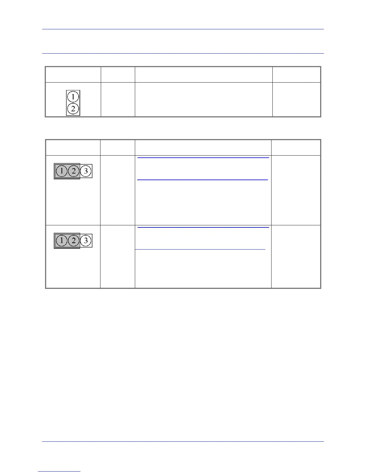
E1 - E2: Machine Output Supply Voltage Configure
E Point and
Physical Layout
CAUTION
The jumper setting must match the type of driver IC,
or damage to the IC will result.
Jump pin 1 to 2 to apply +V (+5V to 24V) to pin 10
of U13 (should be ULN2803A for sink output
configuration) JOPTO machine outputs M01-M08.
Jump pin 2 to 3 to apply GND to pin 10 of U13
(should be UDN2981A for source output
configuration).
CAUTION
The jumper setting must match the type of driver IC,
or damage to the IC will result.
Jump pin 1 to 2 to apply GND to pin 10 of U13
(should be ULN2803A for sink output configuration).
Jump pin 2 to 3 to apply +V (+5V to 24V) to pin 10
of U13 (should be UDN2981A for source output
configuration).