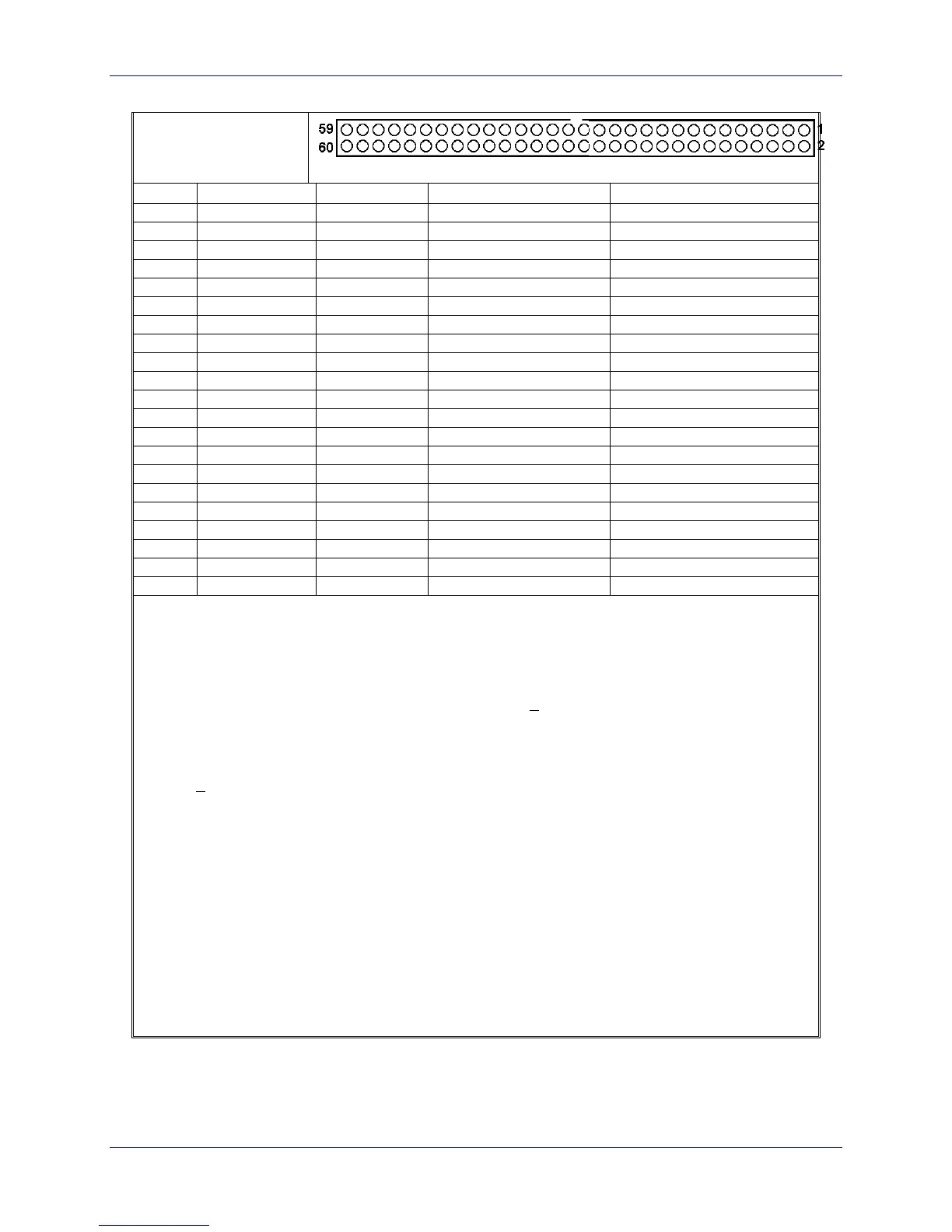
The J7 connector is used to connect the PMAC to the second 4 channels (Channels 5, 6, 7, and 8) of servo
amps, flags, and encoders.
Note 1: In standalone applications, these lines can be used as +5V power supply inputs to power PMAC's
digital circuitry. However, if a terminal block is available on your version of PMAC, it is preferable to
bring the +5V power in through the terminal block.
Note 2: Referenced to digital common (GND). Maximum of + 12V permitted between this signal and its
complement.
Note 3: Leave this input floating if not used (i.e. digital single-ended encoders). In this case, jumper (E18
- 21, E24 - 27) for channel should hold input at 2.5V.
Note 4: + 10V, 10mA max, referenced to analog common (AGND).
Note 5: Leave floating if not used; do not tie to AGND. In this case, AGND is the return line.
Note 6: Functional polarity controlled by jumper(s) E17. Choice between AENA and DIR use controlled
by Ix02 and Ix25.
Note 7: Functional polarity controlled by variable Ix25. Must be conducting to 0V (usually AGND) to
produce a '0' in PMAC software. Automatic fault function can be disabled with Ix25.
Note 8: Pins marked -LIMn should be connected to switches at the positive end of travel. Pins marked
+LIMn should be connected to switches at the negative end of travel.
Note 9: Must be conducting to 0V (usually AGND) for PMAC to consider itself not into this limit.
Automatic limit function can be disabled with Ix25.
Note 10: Functional polarity for homing or other trigger use of HMFLn controlled by Encoder/Flag
Variable 2 (I902, I907, etc.) HMFLn selected for trigger by Encoder/Flag Variable 3 (I903, I908, etc.).
Must be conducting to 0V (usually AGND) to produce a 0 in PMAC software.