PMAC-PCI Hardware Reference
36 Mating Connectors
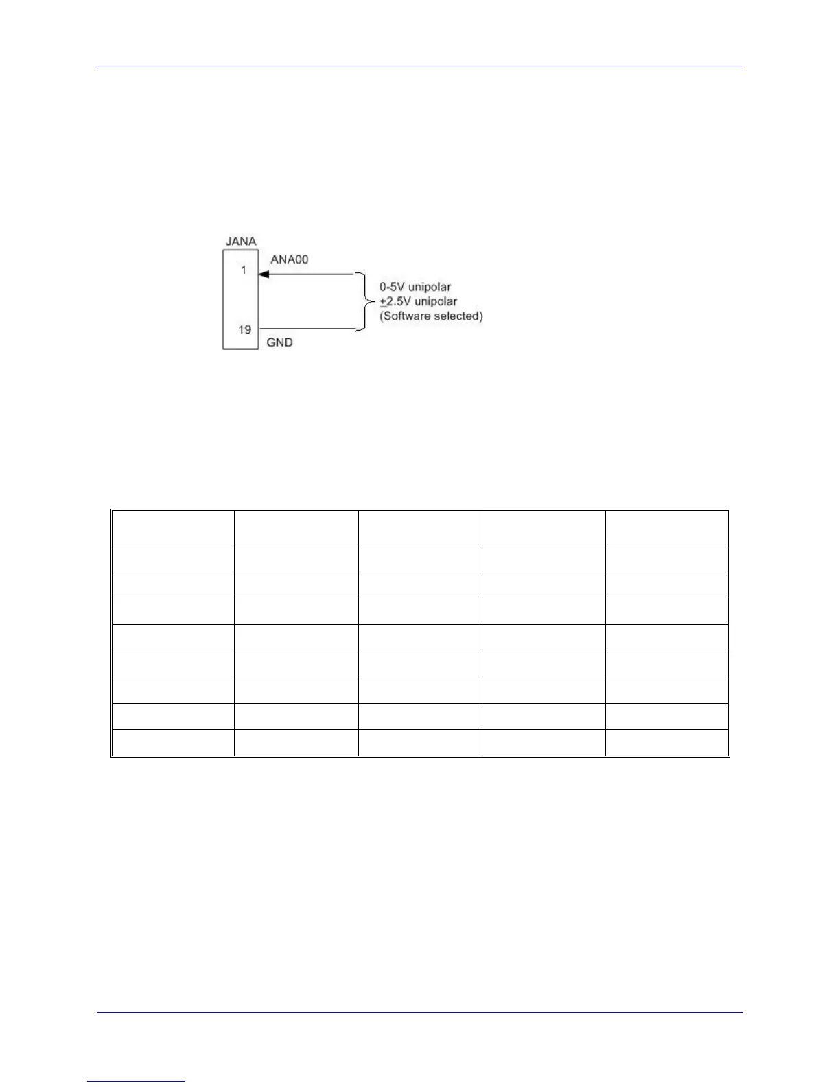
The input is selected and the conversion is started by writing to this same word address Y:$FFC8. A
value of 0 to 7 written into the low 12 bits selects the analog input channel of that number (ANAI00-
ANAI07) to be converted in unipolar mode (0V to +5V). A value of 0 to 7 written into the high 12 bits
selects the analog input channel numbered 8 greater (ANAI08-ANAI15) in unipolar mode. If the value
written into either the low 12 bits or the high 12 bits is 8 higher (8 to 15), the same input channel is
selected, but the conversion is in bipolar mode (-2.5V to +2.5V).
Analog Data Table
PMAC1 PCI firmware automatically selects and reads the channels of the A/D converters in a round-
robin fashion. This function is controlled by a data table (reference Table 10-1) in registers $0708 to
$070F which operates much like the encoder conversion table. The eight X registers contain the channel
select information, and the eight Y registers contain the A/D results. Each X and Y word is split into two
12-bit halves, where the lower 12 bits work with the first A/D converter set (Option 12), and the higher 12
bits work with the second A/D converter set (Option 12A).
where:
CONFIG_W2 is the selection word for the second A/D converter set (Option 12A)
CONFIG_W1 is the selection word for the first A/D converter set (Option 12)
DATA_W2 is the matching A/D data from the second A/D converter set (Option 12A)
DATA_W1 is the matching A/D data from the first A/D converter set (Option 12)
A value of 0-7 in CONFIG_W1 tells PMAC1 PCI to read channel ANAI00-07, respectively, as a 0
to+5V input.
A value of 8-15 in CONFIG_W1 tells PMAC1 PCI to read ANAI00-07, respectively, as a -2.5 to +2.5V
input.