VFD-F Series
DELTA ELECTRONICS, INC. ALL RIGHTS RESERVED
3-8
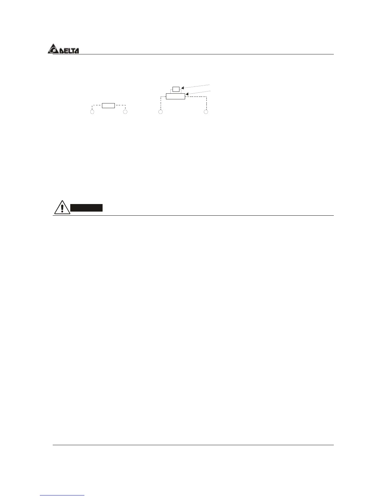
Terminals [+2/B1, B2] for connecting brake resistor and terminals [+2/B1, -] for
connecting external brake unit
Brake unit(optional)
Refer to Appendix B for the use of
special brake resistor/unit
+2/B1
B2
BR
+2/B1
-
VF D B
BR
Brake resistor(optional
Connect a brake resistor or brake unit in applications with frequent deceleration ramps,
short deceleration time, too low brake torque or requiring increased brake torque.
If the AC motor drive has a built-in brake chopper, connect the external brake resistor to
the terminals [
+
2/B1, B2].
Some models of VFD-F series don’t have a built-in brake chopper, please connect an
external optional brake unit and brake resistor.
When not used, please leave the terminals [+2(+2/B1), -] open.
WARNING!
Short-circuiting [B2] or [-] to [+2/B1] can damage the AC motor drive.
 Loading...