8
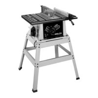
Fig. 7
5. Position table (A) Fig. 7, on the machine as shown.
Align the two holes in the table trunnions (O) with the two
holes in the base (P) of the machine. NOTE: BEFORE
TIGHTENING THE M6x1x45mm SPECIAL SCREWS
(B) AND M6 LOCKNUTS (C) FIG. 7, MAKE SURE THE
TILT SCALE (D), IS POSITIONED INSIDE POINTER (E)
AS SHOWN. ALSO, DO NOT COMPLETELY TIGHTEN
THE M6x1x45mm SPECIAL SCREWS (B) AND M6
LOCKNUTS (C). TABLE MUST BE ABLE TO TILT
FREELY. Fasten the table (A), to the base (P), using the
two M6x1x45mm special screws (B), and M6 locknuts
(C) as shown.
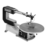
6. Disassemble the handle by unscrewing and remov-
ing screw and spring (F), and handle (G) from locking
stud (H), as shown in Fig. 8. Place a M10 flat washer (J)
on threaded end of stud (H).
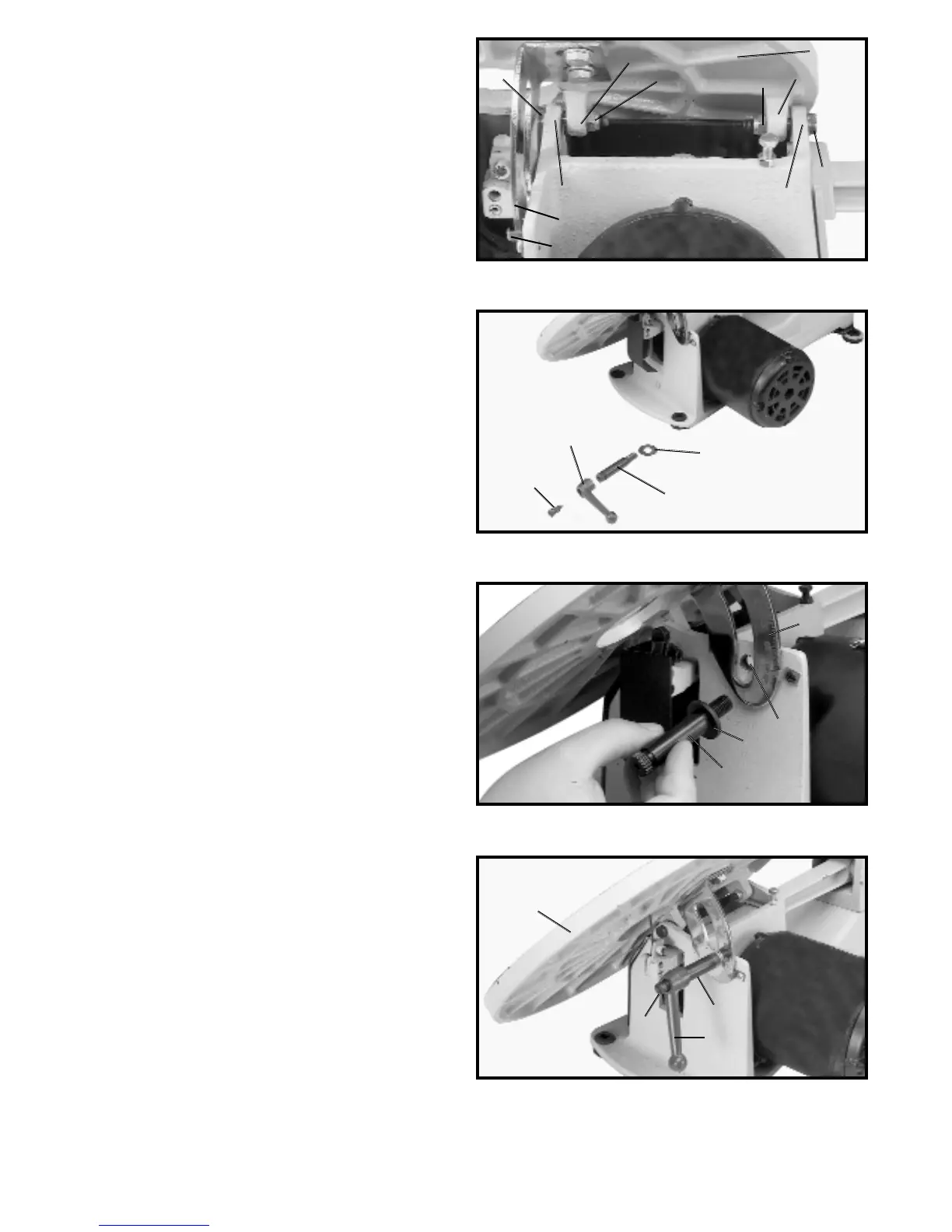
7. Screw threaded end of stud (H) Fig. 9, with the M10
flat washer (J) through slot in angle of tilt scale (D) and
into tapped hole (K).
8. Place handle (G) Fig. 10, onto locking stud (H) and
fasten with screw and spring (F). Move table (A) to the
horizontal position and lock table (A), by turning handle
(G) clockwise.
B
P
O
C
A
C
O
B
P
Fig. 8
F
G
H
J
Fig. 9
Fig. 10
G
F
H
A
D
E
J
H
D
K
 Loading...