6
ASSEMBLY
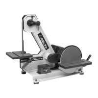
Fig. 1
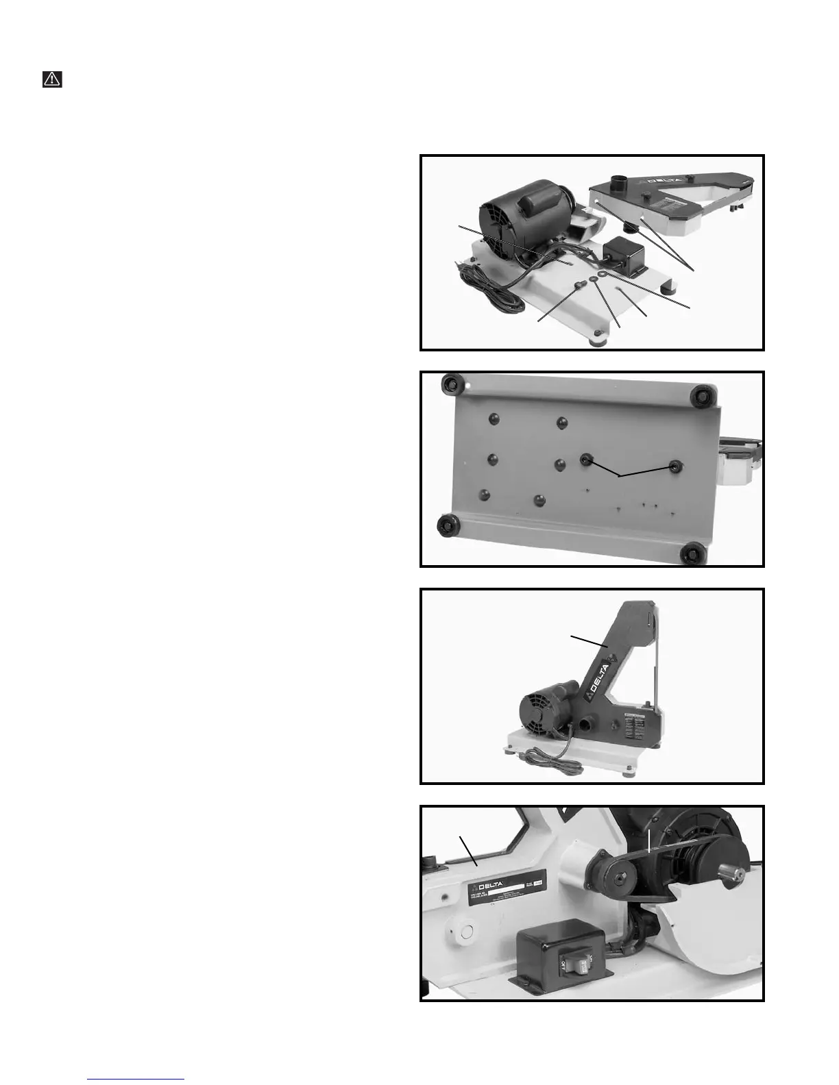
Fig. 2
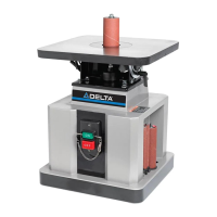
Fig. 3
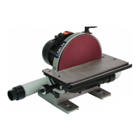
Fig. 4
ASSEMBLING
BELT UNIT TO BASE
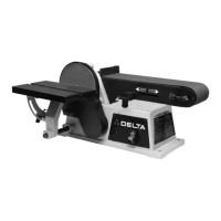
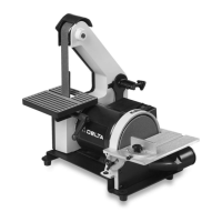
1. Place a 10mm lockwasher (D) Fig. 1, and a 10mm flat
washer (E) onto a M10x20mm hex socket head screw (A)
and insert the screw up through the hole (B) in the base.
Thread the screw into the tapped hole (C) in the bottom
of the belt unit, repeat this process for the remaining
hole. Do not completely tighten the two screws (A) Fig. 2
at this time.
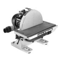
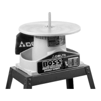
2. Fig. 2, illustrates the two screws (A), inserted into the
two holes in the bottom of the base.
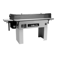
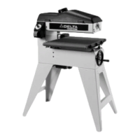
3. Fig. 3, illustrates the belt unit (D) assembled to the
base.
ASSEMBLING DRIVE
BELT AND ADJUSTING
BELT TENSION
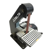
1. DISCONNECT MACHINE FROM POWER SOURCE.
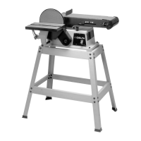
2. Assemble the drive belt (A) Fig. 4, to the two pulleys,
as shown.
3. Slide the belt sander frame assembly (B) Fig. 4,
forward until there is approximately 1/4 to 1/2 inch de-
flection in the belt (A) at the center span of the pulleys
using light finger pressure.
4. Then tighten the two M10X20mm hex socket head
screws (A) Fig. 2, that fasten the belt unit to the base.
A
B
A
D
A
B
B
C
D
E
WARNING: FOR YOUR OWN SAFETY, DO NOT CONNECT THE MACHINE TO THE POWER SOURCE UNTIL
THE MACHINE IS COMPLETELY ASSEMBLED AND YOU READ AND UNDERSTAND THE ENTIRE INSTRUCTION
MANUAL.