7
Fig. 5
Fig. 6
Fig. 7
Fig. 8
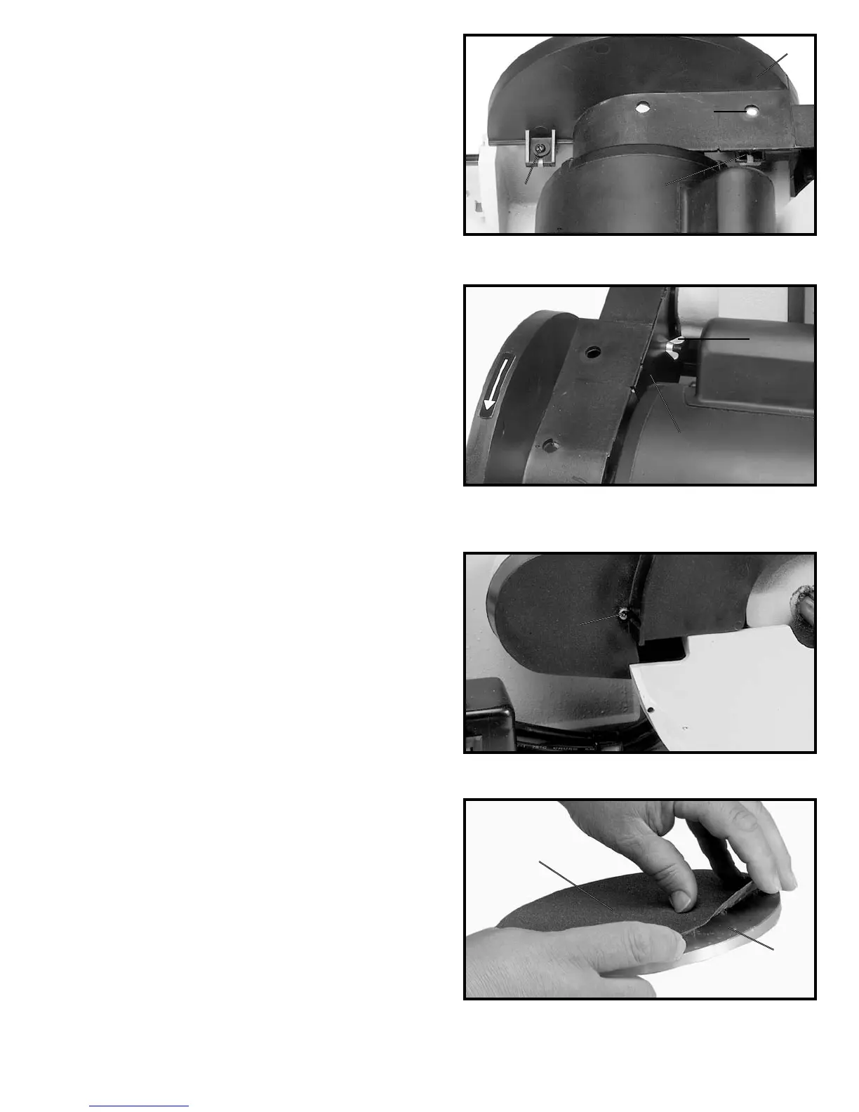
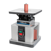
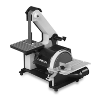
ASSEMBLING GUARD
FOR SANDING DISC
AND BELT AND PULLEYS
1. DISCONNECT MACHINE FROM POWER SOURCE
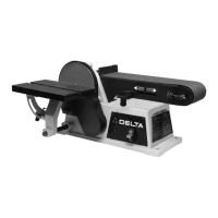
2. Position the guard (A) Fig. 5, in place on the disc unit
frame and fasten in place using the two M4X10mm
cheese head screws (B) and (C) and two 3/16" flat
washers. NOTE: Access to screw (C) is through hole (D)
in top of guard. Do not completely tighten screws (B) and
(C) at this time as the guard must be adjusted to sanding
disc plate.
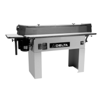
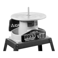
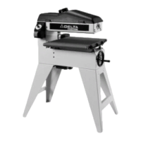
3. Assemble the inside guard (E) Fig. 6, to the guard
assembly using a M4x45mm cheese head screw (F) Fig.
7, and M4 wing nut (G) Fig. 6, as shown.
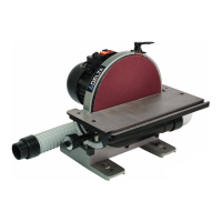
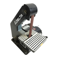
ASSEMBLING SANDING
DISC TO DISC PLATE
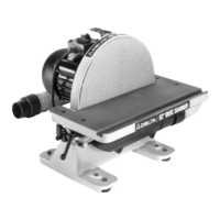
1. Make sure the disc plate (A) Fig. 8, is clean.
2. Peel backing from sanding disc and press the
sanding disc (B) firmly onto the disc plate (A), as shown
in Fig. 8.
A
D
C
B
E
G
F
B
A