9
Fig. 13
Fig. 14
Fig. 15
Fig. 16
ASSEMBLING SANDING
DISC TABLE
1. DISCONNECT MACHINE FROM POWER SOURCE.
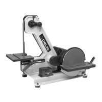
2. Two clamp handles are supplied with your machine,
one for the belt sander table and one for the disc sander
table. Disassemble both handles by unscrewing and re-
moving screw (A), spring (B), and handle (C) from locking
stud (D), as shown in Fig. 13.
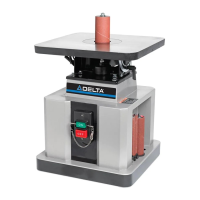
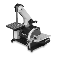
4. Using locking stud (D) Fig. 13, from handle assembly,
and 10mm flat washer (J) Fig. 15, thread locking stud (H)
Fig. 15, into threaded hole in base casting to hold table
assembly (E) in place, as shown.
5. Assemble handle (C) Fig. 15, to locking stud (H) and
fasten with screw (A) and spring (B).
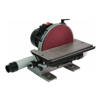
6. Fig. 16, illustrates the locking handle (C) assembled.
NOTE: The locking handle (C) is spring-loaded and can
be repositioned by pulling out the handle and
repositioning it on the serrated stud located underneath
the handle.
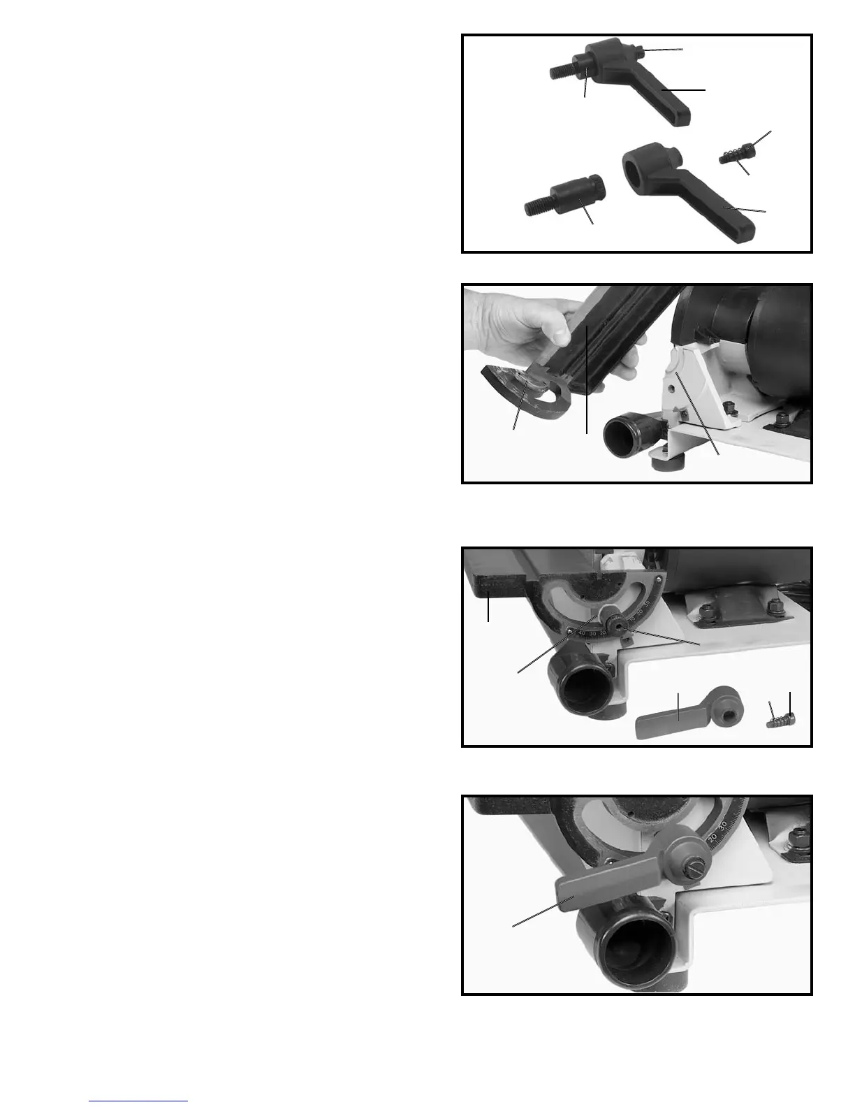
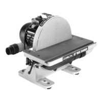
3. Position the disc table (E) Fig. 14, on the disc base
casting, making sure the key (F) on the table bracket is
engaged with the keyway (G) on the base casting.
A
C
D
A
B
C
D
F
E
G
C
A
B
C
H
J
E