19
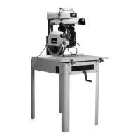
Fig. 39
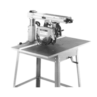
Fig. 40
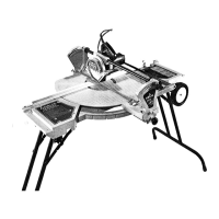
Fig. 41
ADJUSTING CUTTINGHEAD BALL
BEARINGS AGAINST TRACK RODS
The carriage is mounted on four pre-loaded, pre-
lubricated, shielded ball bearings: two on fixed shafts (on
saw blade side of track arm); the other two on adjustable
eccentric shafts.
The ball bearings must ride smoothly and evenly against
the track rods to do accurate work. If wear should ever
develop in the track rods causing “play” between the ball
bearings and the track rods, the ball bearings can be
adjusted as follows:
1. DISCONNECT MACHINE FROM
POWER SOURCE.
2. Move the cuttinghead to the center of the track, and
check to see if any play is present.
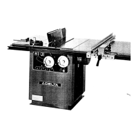
3. To adjust, place special wrench socket (A) Fig. 39,
supplied with the saw, over hexagon nut, located under-
neath the carriage. Place one of the wrenches (B)
supplied, on flats on special wrench socket (A) and
loosen hexagon nut.
4. Loosen set screw (C) Fig. 39, with allen wrench to
release locking action on eccentric shaft.
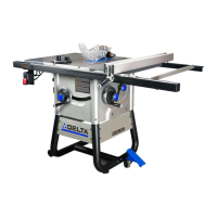
5. Using a small screwdriver (D) Fig. 40, turn screw
slightly until all play is removed.
6. Lock set screw (C) Fig. 39, and tighten hex jam nut
with special socket wrench (A).
7. Use the same procedure to adjust rear bearing.
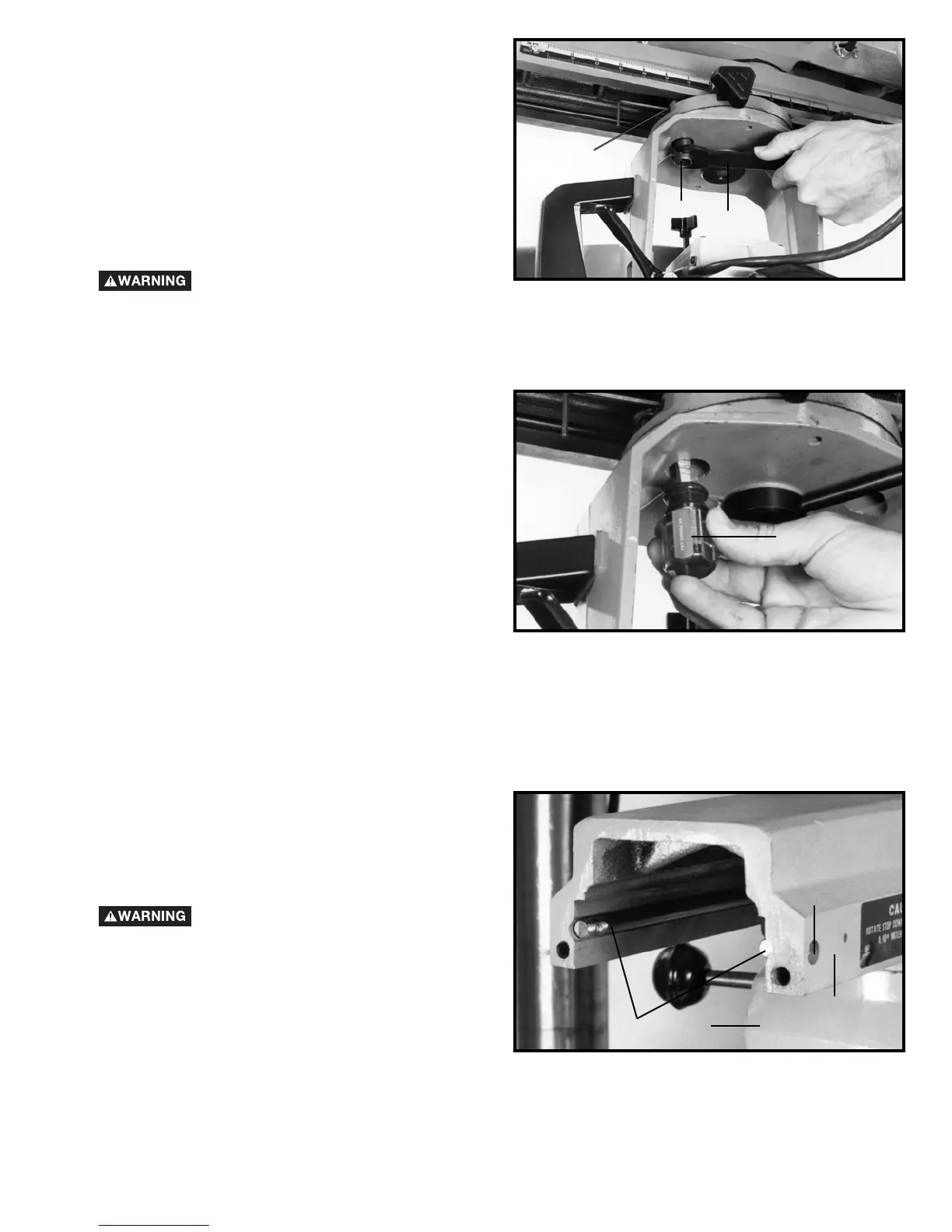
ADJUSTING TRACK RODS
After a period of heavy use the two track rods (A) Fig. 41,
may in time show signs of wear especially where the
cuttinghead is used most often in the track arm. If this
happens you will have an uneven bearing surface for the
cuttinghead bearings.
If an adjustment should ever become necessary proceed
as follows:
1. DISCONNECT MACHINE FROM
POWER SOURCE.
2. Remove rear plate from track arm (B) Fig. 41.
3. Remove the cuttinghead assembly (C) Fig. 41, from
the track arm (B).
4. Remove four screws (D) Fig. 41, one of which is
shown, and rotate track rods (A) 180°.
5. Replace track rods (A) Fig. 41, inside track arm (B)
and fasten with four screws (D).
6. Replace the cuttinghead assembly.
7. Replace rear plate on track arm.
C
A
B
D
A
D
B
C
 Loading...