21
Fig. 46
Fig. 47
Fig. 49
Fig. 48
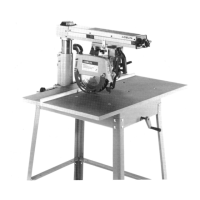
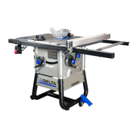
7. When the adjustment is made, turn the bevel clamp
handle (F) Fig. 46, counterclockwise to lock the motor in
position. NOTE: If the bevel clamp handle (F) does not
completely lock the motor, the clamp handle can be re-
positioned by pulling out the handle and repositioning it
on the serrated nut located under the handle.
8. Tighten bolt (D) Fig. 44, and two bolts (C) Fig. 43.
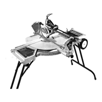
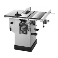
9. Loosen screw (G) Fig. 47. Move pointer (H) to zero
mark on the bevel scale (J). Tighten screw (G).
10. Replace blade guard that was removed in STEP 2.
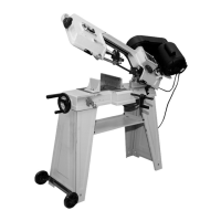
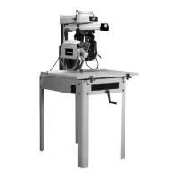
ADJUSTING TRACK ARM CLAMP
HANDLE
The track arm clamp handle (A) should lock the track arm
(B) when the handle is in the position shown in Fig. 48,
and the track arm should be loose when the handle is
pushed back resting on stop (C). If an adjustment to the
track arm handle (A) is necessary, proceed as follows:
1. DISCONNECT MACHINE FROM
POWER SOURCE.
2. Unscrew and remove stop (C) Fig. 48, and unscrew
and remove track arm clamp handle assembly (A).
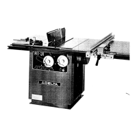
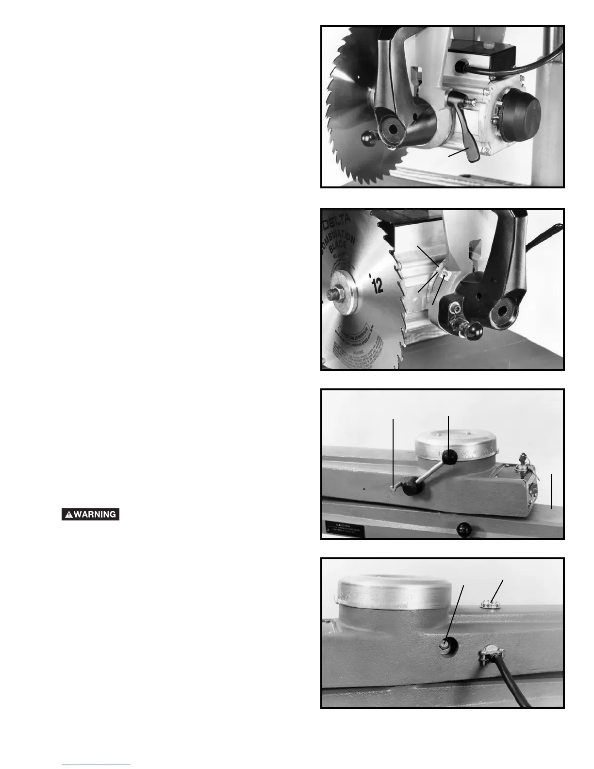
3. Remove clamp (D) Fig. 49, from opposite side of
track arm and change position of bolt head (E).
4. Replace track arm clamping handle assembly (A)
Fig. 48, and check for proper locking position. Make
further adjustment if necessary until clamping handle
locks properly.
5. Replace stop (C) Fig. 48, and cap (D) Fig. 49.
F
G
H
J
A
C
B
E
D
 Loading...