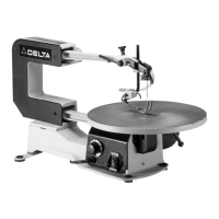
Fig. 14 Fig. 15
TABLE
INSERT
The
table insert (A) can be
assembled
to the
saw
table with the
opening
in the insert
pointing
to the front
of
the table, as
shown
in Fig. 14,
or
to the right of the table, as
shown
in Fig. 15.
With
the table in the level position, 90
degrees
to the blade, the insert (A)
should
be
positioned
as
shown
in Fig. 14.
This
allows for the blade to be pivoted forward
after
it is
unclamped
from
the top blade holder,
enabling
you to
quickly
insert the blade into the next hole in a pattern when
doing
inside
cutting, as you will see later in this manual.
When
tilting the table for bevel
cutting
operations, the insert (A)
should
be
positioned
as
shown
in Fig.
15.
This
allows
clearance
for the blade
when
tilting the table.
A table insert
blank
(B) Fig. 16, is
supplied
as
standard
equipment
with
your
scroll
saw
and can be used
when
cutting
very small
workpieces
to
give
added
support
to
the bottom of the
workpiece.
Simply
cut
a slot into the
blank
and replace the
standard
insert
(A)
with the
blank
(B).
The
slot
cut
into the
blank
(B) will
only
be
as
wide
as
the blade
giving
maximum
support
to the
bottom
of
the
workpiece.
Fig.
16
BLADE BREAKAGE
Blade
breakage
is
usually
caused
by
one
or
more
of
the
following:
1.
Bending
the blade
during
installation.
2.
Improper
blade tension.
3.
Improper
blade
selection
for the
work
being
cut.
4. Forcing the
work
into the blade too rapidly.
5.
Cutting too
sharp
a turn for the blade being used.
6.
Improper
blade speed.
9