The document is an instruction manual for a Delta 12" Variable Speed Wood Lathe, Model 46-700, dated August 1, 1991. It covers assembly, operation, and maintenance of the lathe, as well as safety rules and warranty information.
Function Description
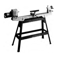
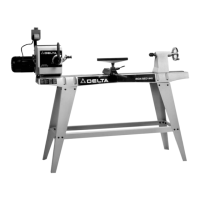
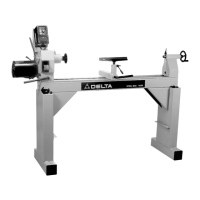
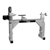
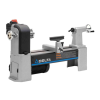
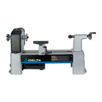
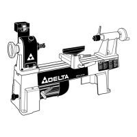
The Delta 12" Variable Speed Wood Lathe (Model 46-700) is designed for wood turning, allowing users to shape wood pieces by rotating them against various cutting tools. It supports both spindle turning (where the workpiece is held between two centers) and faceplate turning (where the workpiece is mounted to a faceplate and rotated). The variable speed feature provides flexibility for different turning operations and wood types.
Important Technical Specifications
- Model: 46-700
- Spindle Speeds: Variable, ranging from 500 to 2000 RPM.
- Power Requirements: A separate electrical circuit protected with a 20 Amp time lag fuse is recommended. For extension cords, 3-wire, 3-prong grounding type plugs and 3-hole receptacles are required. #12 wire for distances up to 100 feet, and #10 wire for distances up to 150 feet.
- Headstock Spur Center: No. 2 Morse Taper shank.
- Tailstock Cup Center: No. 2 Morse Taper shank.
- Tailstock Spindle: 5/16" diameter hollow spindle, with 2 inches of total movement.
- Faceplate Sizes: 3-inch and 6-inch faceplates are mentioned for mounting work.
- Accessory Stand: Model 46-705 stand is an accessory for mounting the lathe.
- Tool Rest Base Extension: Accessory 46-706 off-set base extension for inside turning.
- French Curl Tool Rest: Accessory 46-404 for deeper inside turning operations.
- Hollow Cup Center: Accessory 46-708 for boring holes through the tailstock spindle.
- Lamp Auger: Compatible with the hollow tailstock for boring holes.
- Knockout Bar: Cat. No. 46-905, equipped with a brass plug and comfortable knob, for removing tapered shank spur centers.
Usage Features
- Variable Speed Control: The lathe offers variable spindle speeds from 500 to 2000 RPM, adjustable via a control lever. It is crucial to change speeds only when the lathe is running. Turning the lever clockwise increases speed, and counterclockwise decreases it. The lever is spring-loaded and can be repositioned.
- Headstock Repositioning: The headstock can be slid along the lathe bed and rotated 90 degrees for outboard faceplate turning, accommodating larger workpieces that cannot swing over the lathe bed. This feature enhances versatility for different turning projects.
- Tool Rest Adjustment: The tool rest and its base can be positioned along the lathe bed and adjusted for height, allowing the operator to maintain the optimal 1/8" distance from the workpiece and 1/8" above the centerline. Locking levers secure these adjustments.
- Tailstock Adjustment: The tailstock can be moved lengthwise along the lathe bed and locked in position. Its spindle can be advanced or retracted using a handwheel, with a total movement of two inches. The hollow tailstock spindle allows for boring holes through turnings.
- Work Mounting:
- Between Centers: For spindle turning, work is centered using methods like marking diagonals or setting off distances from edges. The spur center is seated into the workpiece, and the tailstock cup center provides support. Lubrication is recommended for non-ball bearing tailstock centers.
- Faceplate Mounting: For faceplate turning, work can be directly mounted to 3-inch or 6-inch faceplates. For larger pieces or when screws are not permissible, a backing block can be used, sometimes glued with a paper joint for later separation. Smaller work (under 3" diameter) can be mounted on a single screw center.
- Turning Techniques: The manual details various turning operations, including:
- Roughing a Cylinder: Using a large gouge at low speed, starting 2 inches from the tailstock end and working towards it, then rolling the gouge in the opposite direction for the live center end.
- Smoothing a Cylinder: Performed with a large skew chisel, requiring practice to master the cutting point and angle.
- Using the Parting Tool: For cutting-off, making straight incisions, or sizing cuts. It's a scraping tool, pushed into the work, with clearance cuts recommended for deep grooves.
- Squaring an End: Can be done with a parting tool or, for a cleaner cut, with a skew chisel using a nicking cut and clearance cuts.
- Cutting a Shoulder: Involves using a parting tool to reduce wood, then a gouge to clean out waste, and finally a skew chisel for the actual shoulder cut.
- Cutting Small Beads: Can be scraped with a spear chisel or cut with a small skew, involving vertical incisions and rotating the chisel through successive stages.
- Vee Grooves: Similar to bead cutting but without rotation, hinging the skew straight into the work.
- Long Cuts: For convex or straight-tapered surfaces, using a gouge for convex cuts and a skew for tapers, always cutting downhill.
- Cove Cuts: Made with a gouge, starting by laying out the intended cove and removing surplus stock.
- Square Sections: For turning from square to round, emphasizing good centering and using a parting tool, gouge, and skew or spear chisels.
- Safety Features:
- Switch Locking: The switch can be locked in the "OFF" position using a padlock for childproofing and preventing accidental starting.
- Grounding: The tool is equipped with a 3-prong grounding plug to protect the operator from electric shock. Proper grounding instructions are provided, including the use of 3-wire extension cords and, if necessary, temporary adapters connected to a grounded outlet box.
- General Safety Rules: Emphasizes reading the manual, keeping guards in place, wearing eye protection, removing adjusting keys/wrenches, keeping the work area clean, avoiding dangerous environments, keeping children/visitors away, childproofing the workshop, not forcing the tool, using the right tool, wearing proper apparel (no loose clothing, gloves, jewelry), securing work, not overreaching, maintaining tools, disconnecting tools before servicing, using recommended accessories, avoiding accidental starting, never standing on the tool, checking damaged parts, correct direction of feed, never leaving the tool running unattended, avoiding operation under influence of drugs/alcohol/medication, and ensuring power is disconnected during motor mounting/connection.
- Wood Lathe Specific Safety Rules: Includes warnings against operating until fully assembled, seeking advice if unfamiliar, ensuring proper grounding, clearing the lathe bed before turning on, examining setup, proper tool rest adjustment and proximity to workpiece, rotating workpiece by hand to check clearance, never adjusting tool rest while turning, removing tool rest before sanding/polishing, ensuring tailstock center is snug and locked (and lubricated if not ball bearing), never driving workpiece into drive center when in headstock, never loosening tailstock spindle/tailstock while turning, ensuring workpiece is securely fastened to faceplate, ensuring screw fasteners don't interfere with turning tool, rough cutting workpiece before faceplate mounting, tightening all clamp handles, examining workpiece for flaws, not jamming tool or taking too big a cut, using lowest speed for new workpiece, operating at recommended speeds, making all adjustments with power "OFF" (except speed changes while running), disconnecting for repairs/cleaning, cleaning work area, and replacing damaged parts.
Maintenance Features
- Replacing Variable Speed Drive Belt: Detailed instructions are provided for replacing the drive belt, which involves:
- Operating the lathe at high speed, then turning off and disconnecting power.
- Removing screws from the right and left sides of the headstock.
- Removing both left and right half headstock covers.
- Turning the variable speed control handle counterclockwise to loosen belt tension.
- Removing three screws supporting the motor, with a caution to support the motor to prevent it from falling.
- Removing the motor and motor bracket, and the motor pulley half.
- Marking the spindle pulley hub's location on the spindle with a pencil.
- Loosening the set screw and moving the spindle pulley half to the left, with a caution to hold it due to spring pressure.
- Removing the snap ring and spring washer from the inboard end of the spindle.
- Pushing the spindle assembly to the right to create clearance for belt removal, possibly tapping with a dowel rod.
- Assembling the new belt and reassembling the spindle assembly in the headstock.
- Replacing the spindle assembly, aligning the pulley hub with the pencil mark, tightening the set screw (again with caution for spring pressure), and manually moving the pulley half to the left to create slack for assembling the belt to the motor pulley.
- Reassembling the complete headstock assembly by reversing the disassembly steps.
- General Maintenance: The manual advises keeping tools sharp and clean, following instructions for lubricating and changing accessories, and cleaning the machine before leaving it.
- Part and Service Assistance: Delta provides a Parts Distribution Center in Memphis, TN, with over 15,000 parts. Customer Service Representatives are available weekdays from 8:00 A.M to 5:00 P.M. Memphis time via phone (901) 363-8800 or a toll-free hotline (800-223-PART) and FAX (800-535-6488).
- Warranty: A Two Year Limited Warranty covers repair or replacement of defective workmanship or material, provided the product is returned prepaid to a Delta factory service center or authorized service station with proof of purchase. The warranty does not cover normal wear, misuse, abuse, unauthorized repair/alteration, or incidental/consequential damages.