Chapter 7 Motion Control ASDA-M
7-32 Revision December, 2014
table
P5-81.
Data Size of E-Cam
table
It is set by P5-82. 720 points is the maximum and 5 points is
the minimum.
Data Format of
E-Cam table
32-bit signed value.
Data Content of
E-Cam table
Save the position of slave axis (User unit, PUU)
Features of E-Cam
The operation of
E-Cam position
The master axis operates by incremental command input.
The slave axis issues position command incrementally.
The start and the end of E-Cam curve profile could not
always be the same. It depends on the value of E-Cam
table.
The command is interpolated by cubic curve. The torque on
each point will be smoothly connected because of quadratic
differential operation.
DO.CAM_AREA
(DO no.= 0x18)
Digital Output (DO): CAM_AREA. If this DO is ON, it means
the E-Cam axis is in the setting area.
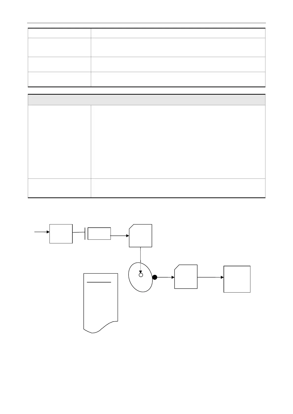
E-Cam provided by this servo drive and below is its functional diagram:
(pulse)
Pulse command
Slave axis
(PUU)
Slave axis
Clutch
Gear box
#2
P5-88.Y
setting
value
P5-88.ZU engaged
method
P5-87 lead pulse
P5-89 Engaged
distance
P5-84: Pulse number sent by master axis
P5-83: E-cam rotation cycle
P5-81: Table address
P5-82: Data amount N
P5-85: Entering point
P5-19: Table scale
Data array
…..
POS 0
POS 1
~
P1-44: gear ratio
(numerator)
P1-45: gear ratio
(denominator)
Master
axis
P5-88.X
setting
value
Position
controller
E-cam axis
Cam
Gear box
#1
 Loading...