8
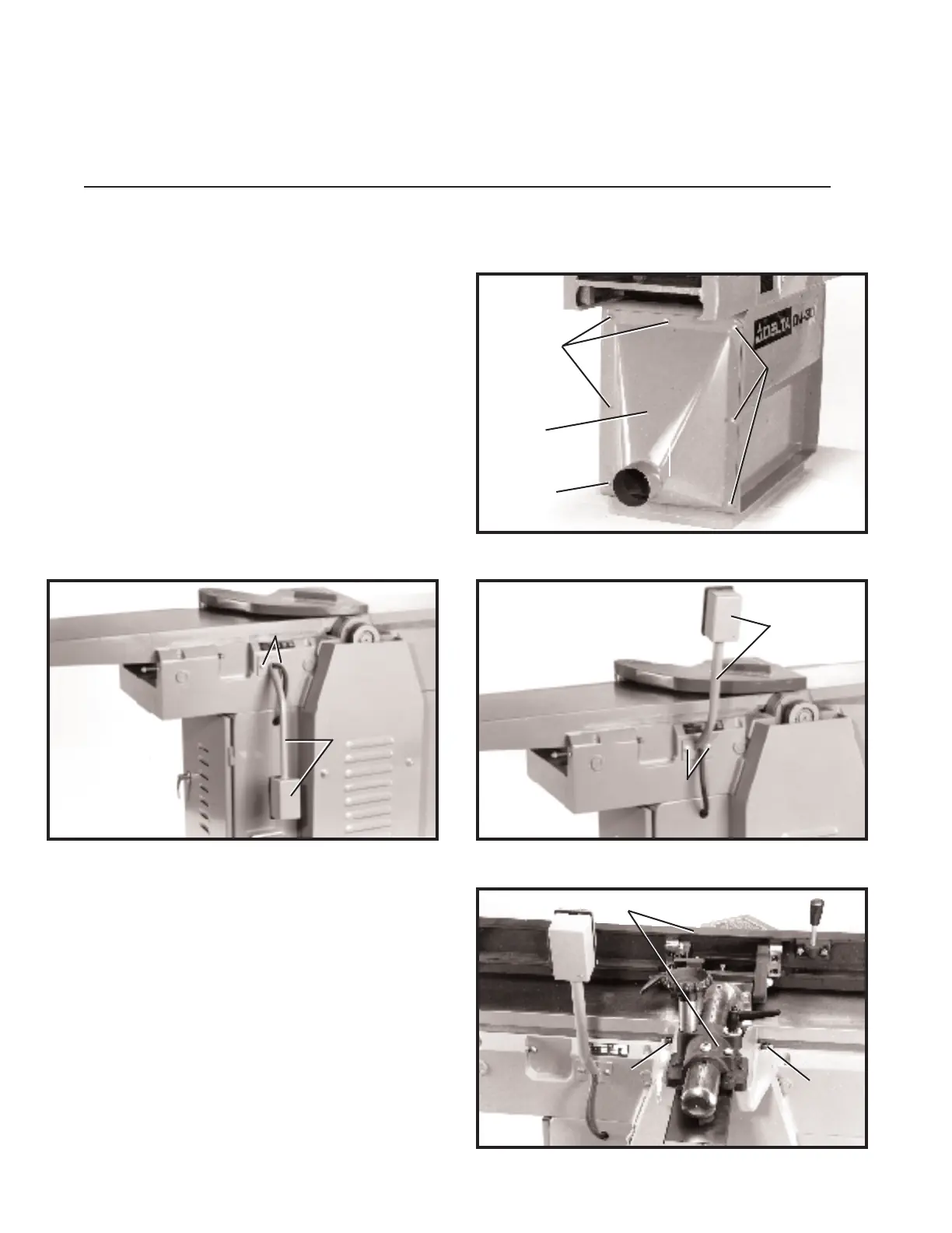
ASSEMBLING DUST HOOD
1. Assemble the dust hood (A) Fig. 8, to the out feed
end of the jointer base using the seven 5/8 long button
head screws (B) as shown.
SELECTING FLOOR SPA C E
It is import ant that the machine be set on a solid, level foundation. If rocking occurs,
place met al shims at the corners between the base and the floor. Lag screws or bolt s
may be used if desired to secure the machine to the floor using the same holes that
fastened the machine to the shipping skid.
ASSEMBLY INSTRUCTIONS
Fig. 1 1
Fig. 8
Fig. 9 Fig. 10
ASSEMBLING
JOINTER FENCE
1. Assemble the jointer fence assembly (A) Fig. 1 1, to
the machine cabinet, as shown, using the two 1-1/8
long screws (B) and flat washers supplied.
MOVING START-STO P
SWITCH TO THE UP POSITION
1. For shipping purposes, the st art-stop switch and
switch arm (A) is shipped in the down position, as shown
in Fig. 9. Simply remove the two screws (B) Fig. 9, rot ate
switch and switch arm (A) 180 degrees, as shown in
Fig. 10, and replace the two screws (B).
A
B
B
B
A
B
A
B
B
B
A
 Loading...