Chapter 5 CPU and Module Devices
5-37
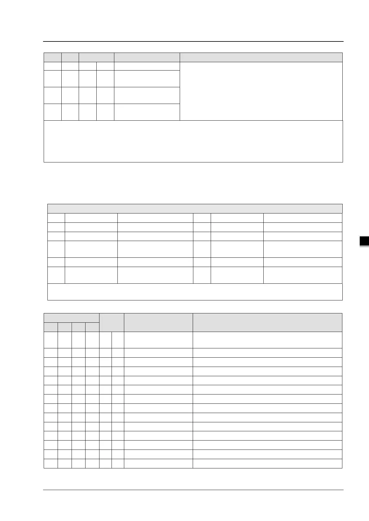
111 111 O R/W
Set value of CH4 lower
112 O R/W
Set value of CH5 lower
113 O R/W
Set value of CH6 lower
O: When CR#41 is set to H’5678, the set value of CR will be saved.
X: Set value will not be saved.
R: You can use FROM instruction to read data.
W: You can use TO instruction to write data.
※ CR#0 for module reset
You can use CR#0 to reset all the settings by simply writing H’4352 in CR#0 and wait for one second before turning the
power OFF and then ON again, all the modules connected will be initialized. It is suggested to connect to only one module
for module reset.
※ CR#43: Error status value. See the table below:
bit2 K4 (H’4) Upper/lower bound error bit10 K1024 (H’0400) Sampling range error
bit3 K8 (H’8) CH1 Conversion error bit11 K2048 (H’0800)
Upper / lower bound setting
error
Set value changing prohibited
bit5 K32 (H’20) CH3 Conversion error bit13 K8192 (H’2000)
Communication breakdown on
Note: Each error status is determined by the corresponding bit (b0 ~ b13) and there may be more than 2 errors
occurring at the same time. 0 = normal; 1 = error
PID Control Registers
Attrib. Register content Description
120
140 160 180 O R/W
Set temperature value
Please set the temperature value according to proper range
of each sensor type. Default = K0
Range: K1 ~ K30 (s). Default = K2
P
Proportional control constant. Default = K121
I
Integral constant. Default = K2,098
124
144 164 184 O R/W
K
D
Derivative constant. Default = K-29
125
145 165 185 O R/W
Upper limit of I value Upper limit of I value. Default = K0
126
146 166 186 O R/W
Lower limit of I value Lower limit of I value. Default = K0
Current accumulated offset value
0: Heater, 1: Cooler. Default = K0
Upper limit of output. Default = K32,000
Lower limit of output. Default = K0
Output percentage (Unit: 0.1%)
Width of control output. Unit: ms
Cycle of control output. Unit: ms

 Loading...


