DVP-ES3 Series Operation Manual
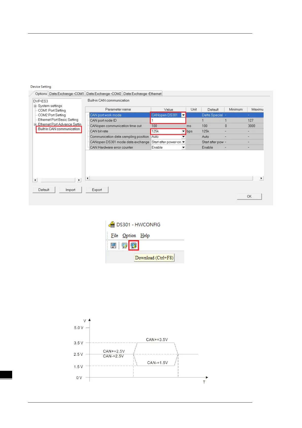
3. Select the working mode, node ID and the bit rate for DVP-ES3.
* Working mode: CANopen DS301
* Node ID: 1
* Bit rate: 125k bps (the default, or you can select your own bit rate)
4. When finished, click the Download button on the toolbar to download the settings to the PLC.
10.2.4 The CAN Interface and Network Topology
10.2.4.1 Definitions of the CAN Signal and Data Types
The CAN signal is a differential signal. The voltage of the signal is the voltage difference between CAN+ and
CAN-. The CAN+ and CAN- voltages take SG as a reference point. The CAN network can be in one of two
states. One state is a dominant level, and is indicated by the logical “0”. The other state is a recessive level,
and is indicated by the logical “1”. The CAN signal level shows below.

 Loading...


