Chapter 10 CANopen Function and Operation
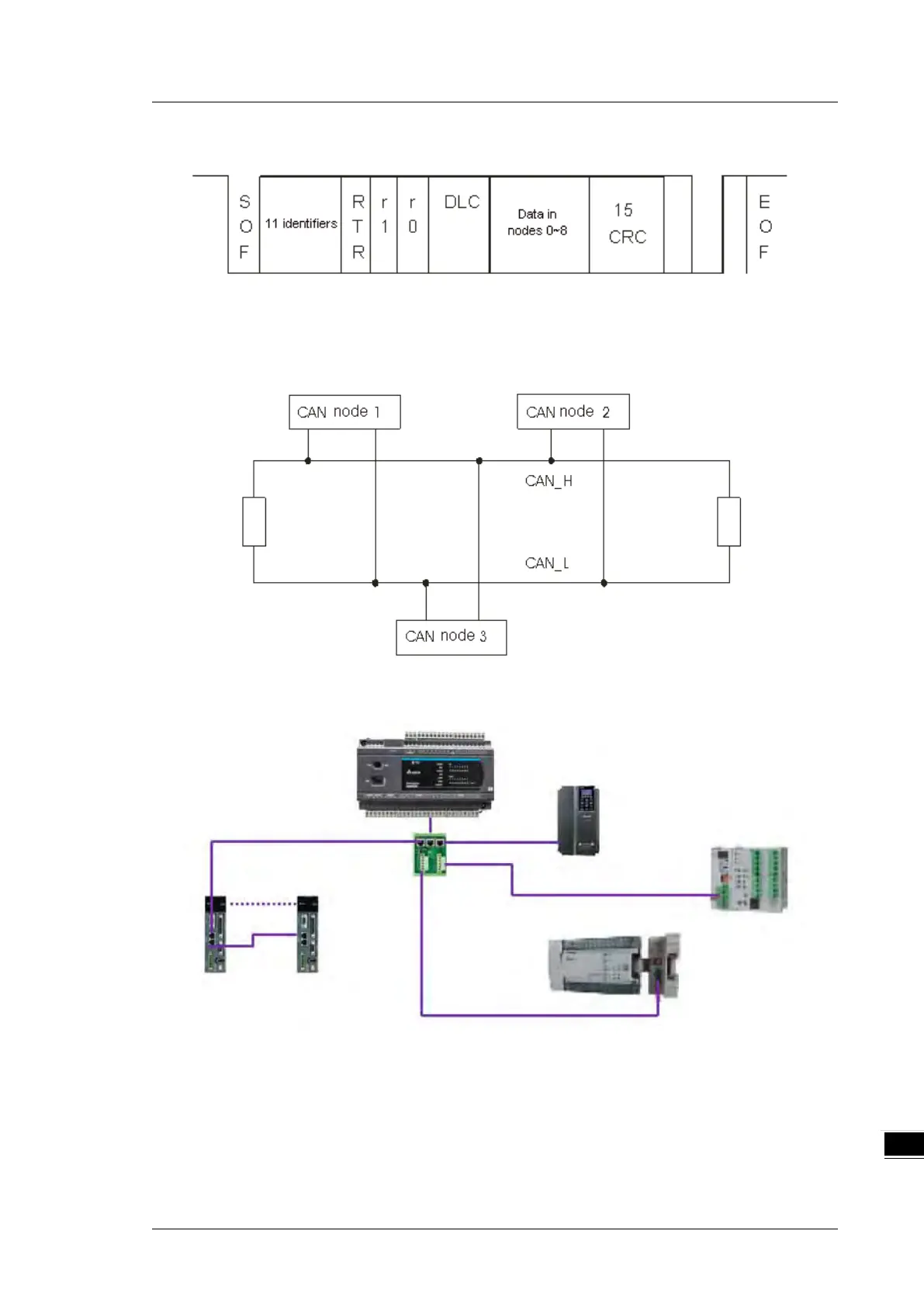
The following picture shows the data frame format. The CAN nodes transmit the CAN messages to the
network from left to right.
10.2.4.2 The CAN Network Endpoint and the Topology Structure
In order to make the CAN communication more stable, the two endpoints of the CAN network are connected
to 120 ohm terminal resistors. The topology structure of the CAN network appears below.
10.2.4.3 The Topology Structure of the CANopen Network
1) Use standard Delta cables when wiring the CANopen network. These cables are the thick cable
UC-DN01Z-01A, the thin cable UC-DN01Z-02A, and the thin cable UC-DN01Z-02A. Separate the
communication cables from any power cables to avoid interference.
2) Connect the CAN+ (white) and CAN- (blue), which are at the endpoints of the network, to 120 ohm
resistors. Purchase the standard Delta terminal resistor (TAP-TR01) for use with the other devices and
the RJ45 connecter.

 Loading...


