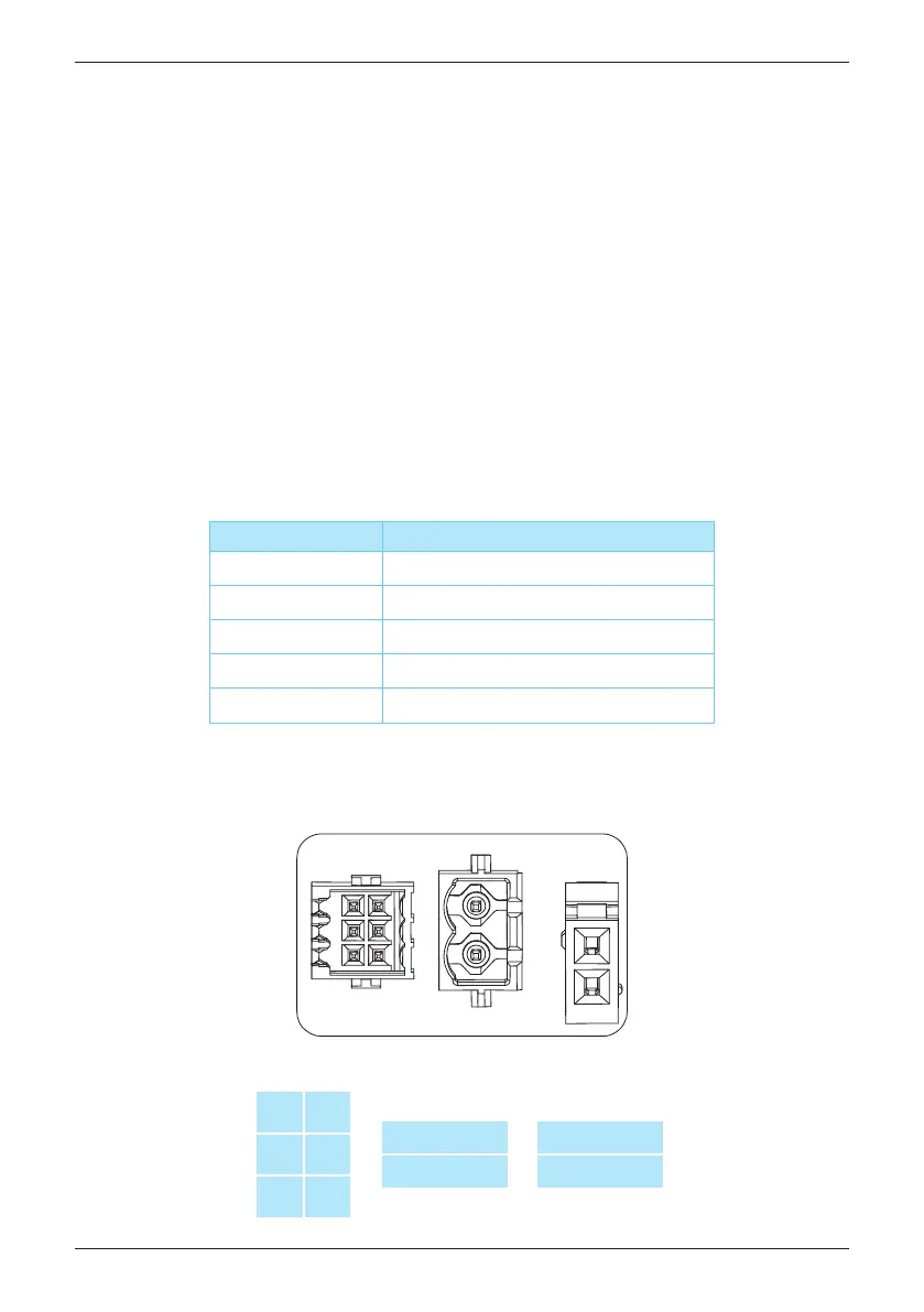
Figure 6-7 : Digital input, Dry contact & Power meter
Short pins
Inverter behavior (AU)
D6 & D2
D6 & D1
D6 & D3
D6 & D4
D6 & D5
DRM 7 - Power de-rating to 75%
DRM 5 - Power de-rating to 0%
DRM 6 - Power de-rating to 50%
DRM 8 - Power de-rating to 100%
DRM 0 - Disconnect from grid
• Conductor cross-section: 0.205 mm² (AWG24) ~ 0.081 mm². (AWG28)
• Outside diameter of cable: 3.8mm ~ 5.2mm
• Please refer to UL 2464 computer cable guideline
D1
D2
D3
D4
D5
D6
Dry contact
Dry contact
Power meter
Power meter
To implementation of power management, the digital input interface receives the
specifications of the network operator via a ripple control receiver.
• Australia and New Zealand:
The inverter support the demand response mode (DRMs).
DRM 0 - Operate the disconnection device.
DRM 5 - Do not generate power.
DRM 6 - Do not generate at more than 50% of rated power.
DRM 7 - Do not generate at more than 75% of rated power.
And sink reactive power.
DRM 8 - Increase power generation.
(subject to constraints from other active DRMs)
• Customer : User defined.
The inverter can detect the state of the relay of the ripple control receiver.
The information which relay shall be controlled parameter by the network operator.
6.9.2 Digital Input
Active/Reactive Power Control and LVRT (Optional)
38