Do you have a question about the Delta (Model TS220LS) and is the answer not in the manual?
Indicates an imminently hazardous situation which, if not avoided, will result in death or serious injury.
Indicates a potentially hazardous situation which, if not avoided, could result in death or serious injury.
Indicates a potentially hazardous situation which, if not avoided, may result in minor or moderate injury.
Potentially hazardous situation which, if not avoided, may result in property damage.
General woodworking safety instructions for operating the machine safely and minimizing personal injury.
Warning about using the machine only for its designed applications and not modifying it.
Do not operate the machine until it is completely assembled and installed according to instructions.
Obtain advice from a supervisor or qualified person if you are not familiar with the machine's operation.
Follow all wiring codes and recommended electrical connections for safe operation.
Always use guards, splitter, and anti-kickback fingers whenever possible to prevent kickback and injury.
Use a separate electrical circuit, not less than #12 wire, protected by a 20 Amp time lag fuse.
Warning against exposing the machine to rain or operating it in damp locations due to electric shock risk.
The machine is wired for 120 volt, 60 HZ alternating current. Ensure switch is OFF before connecting.
The machine must be grounded while in use to protect the operator from electric shock.
Grounded machines require a properly installed and grounded outlet matching the equipment-grounding conductor.
Temporary adapters may be used for 2-conductor receptacles until a grounded outlet is installed, but not in Canada.
The motor is dual voltage (120/240V) and can be reconnected for 240 volt single phase operation.
Use proper, good condition, 3-wire extension cords with grounding plugs and matching receptacles.
Charts provide recommended wire gauge for extension cords based on amperage, voltage, and length.
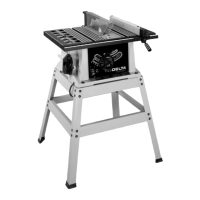
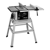
Overview of the Delta ShopMaster TS220LS table saw, highlighting its features, capacity, and included components.
Instructions for unpacking the machine, removing protective coating with kerosene, and applying paste wax.
A list of the table saw components and their corresponding numbers for assembly reference.
Comprehensive identification of all table saw assembly parts shown in Fig. 3, with numerical labels.
Identification of all stand components shown in Fig. 4, including legs, brackets, feet, and hardware.
Warning: Do not connect power until fully assembled and manual is understood.
Detailed steps for assembling the stand components, including brackets and feet, following diagram Fig. 4A.
Procedures for mounting the table saw onto the assembled stand, including alignment and tightening hardware.
Insert the cheese head screw through the handle and thread it into the handwheel clockwise.
Assemble the handwheel to the shaft, ensuring the flat surfaces align correctly.
Secure the handwheel to the shaft using the flat head screw as shown in Fig. 8.
Ensure proper alignment of the guard/splitter to the blade and loosely attach the splitter support bracket.
Mount the splitter bracket to the pivot rod using the specified screw and washers, without fully tightening.
Position the splitter onto the support bracket, ensuring protrusions align with the splitter's slot.
Assemble the splitter to the splitter support bracket using the specified screw and washers.
Fasten the splitter to the support bracket using a flat washer, lockwasher, and wing nut, ensuring a 1/8" gap.
Check the splitter alignment with the saw blade using a straight edge and adjust as necessary.
Once the splitter is properly aligned, tighten all screws to secure the assembly.
Attach the extension wing to the saw table and ensure its edges are level before final tightening.
Fasten the guide rail to both the saw table and extension wing using the specified hardware and tighten securely.
Install the rip fence by threading the handle, lowering it onto the table, and locking it in place with the lever.
Insert the miter gage bar into the table's T-slot groove for stable positioning and guidance.
Assemble the spring clip to the miter gage holder using a screw, lockwasher, and hex nut.
Assemble the miter gage holder to the left side of the saw cabinet using pan head screws and washers.
Figure 30 shows the miter gage inserted into its holder for storage when not in use.
Attach outfeed support brackets to the table and insert rods, securing them with screws and washers.
Secure the outfeed support to the rods and position it until it contacts the splitter/guard assembly, then tighten hardware.
How to start, stop, and securely lock the saw's switch to prevent unauthorized use.
Adjust blade height using the handwheel and ensure the blade tilting lock handle is engaged during cutting.
Procedure to reset the motor's overload relay if it trips due to excessive load or low voltage.
Loosen the tilt lock handle to adjust the blade angle and ensure it is locked during cutting.
Procedure to adjust the 90 and 45-degree positive stops for accurate blade positioning after disconnecting power.
Learn to move, position, and lock the rip fence on the table using its lever.
Align the rip fence to the miter slot and adjust its clamping action for proper operation and safety.
Use the miter gage to position and guide the workpiece for accurate cross-cuts.
Adjust the miter gage's index stops for 90 and 45-degree angles by manipulating lock nuts and screws.
Check and adjust blade parallelism to miter gage slots by measuring at front and rear, then adjusting screws.
Procedure to change the saw blade, including disconnecting power, removing the old blade, and installing the new blade.
Warning: Use only specified 10" blades rated for 5000+ RPM with 5/8" arbor holes.
Warning: Use of unrecommended accessories can be hazardous and increase injury risk.
Utilize the miter gage to position and guide the workpiece for accurate cross-cuts.
Employ safe techniques by holding work firmly, supporting the main piece, and using auxiliary facings.
Never use the fence as a cross-cutting gage; use a clamped block as a cut-off gage with proper positioning.
Use the rip fence for lengthwise cuts, holding work against it, and never stand in the cut line.
Use push sticks for ripping narrow pieces and consider auxiliary facings for safety and control.
Extend outfeed support for boards longer than three feet to prevent them from falling off the table.
Wood facings on the rip fence are used for special operations to improve performance and safety.
Remove guard/splitter, note maximum width, and prepare dado head sets for cutting grooves.
Attach the dado head set to the arbor and use the special table insert, never the standard one.
Remove guard/splitter, avoid bevel positions, use miter gage guide, and reinstall guard after use.
Construct featherboards from wood using specified dimensions and attach them to fence/table to guide work and prevent kickbacks.
Use featherboards for non-thru-sawing operations where guards are removed, and always replace guards afterward.
Make push sticks from scrap material following Fig. 61 pattern for completing feed on narrow rips and preventing hand injury.
A complete line of accessories is available from Delta suppliers, service centers, and their website.
Warning: Use of unrecommended accessories can be hazardous and increase injury risk.
Delta machines and accessories are high quality and serviced by authorized centers; contact for information.
Details of the Two Year Limited New Product Warranty, covering repair or replacement of defective parts.
Lists locations of Porter-Cable • Delta Service Centers for parts and repair in the US and Canada.
Information on locating authorized service stations via telephone numbers provided.
Lists various trademarks associated with Porter-Cable • Delta products.
| Type | Table Saw |
|---|---|
| Motor Power | 1.5 HP |
| Blade Diameter | 10 inches |
| Voltage | 120V |
| Bevel Capacity | 0 - 45 degrees |
| Arbor Size | 5/8 inches |
| Max Cut Depth at 45 degrees | 2-1/4 inches |
| Dust Port Size | 2.5 inches |